MB175cT1 - 1
1173580
B
au
m
er
_H
O
G
S
75
-C
-T
1_
II_
D
E
-E
N
(1
6A
2)
Montage- und Betriebsanleitung
Installation and operating instructions
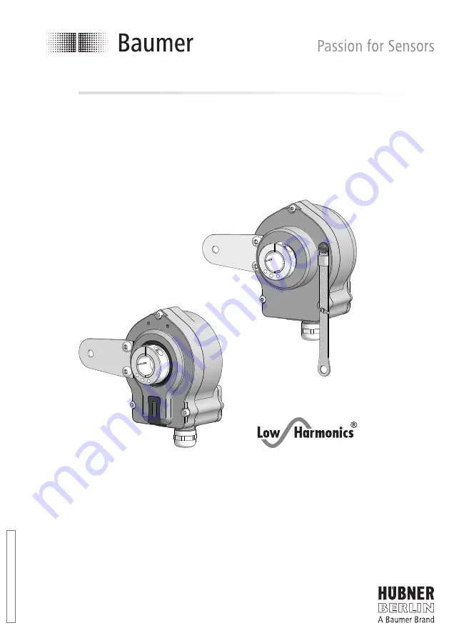
HOGS 75
Sinus Drehgeber
Version mit Stützblech für eine Drehmomentstütze
Sine encoder
Version with support plate for a torque arm


