background image

11 

Baumer_GTF7_II_DE-EN (17A1)  

MB011 - 11055617

5


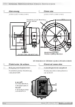
Abmessung  


(80852, 80876, 80880, 80881)

5


Dimension  


(80852, 80876, 80880, 80881)

All dimensions in millimeters (unless otherwise stated)

Drehrichtung positiv

Positive rotating direction

5-6


Abmessung - Elektrischer Anschluss

 / Dimension - Electrical connection

6


Elektrischer Anschluss  

6.1


Belegung Anschlussklemmen  


Polarität bei positiver Drehrichtung, 


siehe Abschnitt 5.

6


Electrical connection  

6.1


Connecting terminal assignment  


Polarity at positive rotating direction,   


see section 5.

Ansicht 

X

Anschlussklemmen, 

siehe Abschnitt 4.6.

View 

X

Connecting terminal, 

see section 4.6.

Passfeder je nach Bestellung

Key as ordered

_

+

Содержание HUBNER BERLIN GTF 7

Страница 1: ...MB011 11055617 Baumer_GTF7_II_DE EN 17A1 GTF 7 Tachogenerator Montage und Betriebsanleitung Installation and operating instructions ...

Страница 2: ...hritt 2 7 4 3 Schritt 3 8 4 4 Schritt 4 8 4 5 Max zulässige Anbaufehler unter Verwendung der Baumer Hübner Federscheiben Kupplung K 35 9 4 6 Schritt 5 10 5 Abmessung 11 6 Elektrischer Anschluss 11 6 1 Belegung Anschlussklemmen 11 7 Betrieb und Wartung 12 7 1 Austausch der Kohlebürsten 12 8 Demontage 13 8 1 Schritt 1 13 8 2 Schritt 2 14 8 3 Schritt 3 14 8 4 Schritt 4 14 9 Technische Daten 15 9 1 Te...

Страница 3: ... 8 4 4 Step 4 8 4 5 Max permissible mounting tolerance when the Baumer Hübner K 35 spring disk coupling is used 9 4 6 Step 5 10 5 Dimension 11 6 Electrical connection 11 6 1 Connecting terminal assignment 11 7 Operation and maintenance 12 7 1 Replace of the carbon brushes 12 8 Dismounting 13 8 1 Step 1 13 8 2 Step 2 14 8 3 Step 3 14 8 4 Step 4 14 9 Technical data 17 9 1 Technical data electrical r...

Страница 4: ... liegt zwischen 15 C bis 70 C 1 5 Der Betriebstemperaturbereich des Gerätes liegt zwischen 30 C bis 130 C am Gehäuse gemessen 1 6 EU Konformitätserklärung gemäß den europäischen Richtlinien 1 7 Wir gewähren 2 Jahre Gewährleistung im Rahmen der Bedingungen des Zentralverbandes der Elektroindustrie ZVEI 1 8 Der Tachogenerator darf nur wie in dieser Anleitung beschrieben geöffnet werden Reparaturen o...

Страница 5: ...d 70 C 1 5 The operating temperature range of the device is between 30 C and 130 C measured at the housing 1 6 EU Declaration of Conformity meeting to the European Directives 1 7 We grant a 2 year warranty in accordance with the regulations of the ZVEI Central Association of the German Electrical Industry 1 8 The tachogenerator may be only opened as described in this instruction Repair or mainte n...

Страница 6: ...les leichtgängig zusam menfügen Für die Demontage geeignetes Abziehwerkzeug benutzen 2 4 Zerstörungsgefahr durch Verschmutzung Schmutz kann im Tachogenerator zu dessen Beschädigung führen Während aller Arbeiten am geöffneten Tachogenerator auf absolute Sauberkeit achten Bei der Demontage niemals Öl oder Fett in das Innere des Tachogenerators gelangen lassen 2 5 Zerstörungsgefahr durch klebende Flü...

Страница 7: ...ly is simple when correct procedure is followed Use suitable puller for disassembly 2 4 Risk of destruction due to contamination Dirt penetrating inside the tachogenerator can damage the tachogenerator Absolute cleanliness must be maintained when carrying out any work on the open tachogen erator When dismantling never allow lubricants to penetrate the tachogenerator 2 5 Risk of destruction due to ...

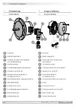
Страница 8: ...7 Kabelverschraubung M16x1 5 für Kabel ø5 9 mm 8 Anschlussklemmen siehe Abschnitt 6 1 9 Abschlussdeckel 10 O Ring 3 5x1 5 mm 11 Torx Befestigungsschraube M3 12 Bürstenhalterring 13 Kohlebürsten 4x 1 Housing 2 EURO flange B10 3 Solid shaft with or without key As ordered 4 Terminal box cover 5 Fixing screw with torx drive M3x25 6 Washer A 3 2 DIN 125 7 Cable gland M16x1 5 for cable ø5 9 mm 8 Connect...

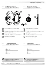
Страница 9: ...7 Anschlusskabel ø5 9 mm 14 Installation fitting customized 15 Fixing screws for installation fitting ISO 4017 M6x16 mm 16 Spring disk coupling K 35 available as accessory see section 4 5 17 Connecting cable ø5 9 mm 14 16 15 17 12x Vorbereitung Preparation 3 3 3 Erforderliches Werkzeug nicht im Lieferumfang enthalten 3 3 Required tools not included in scope of delivery 18 Werkzeugset als Zubehör e...

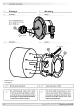
Страница 10: ...nt Max tightening torque Mt 100 Ncm 4 2 Step 2 16 15 14 Die Antriebswelle sollte einen mög lichst kleinen Rundlauffehler aufwei sen Der Anbau an den Antrieb muss mit möglichst geringem Winkelfehler und Parallelversatz erfolgen The drive shaft should have as less runout as possible The tachogenera tor must be mounted on the drive with the least possible angular error and parallel misalignment 2 5 m...

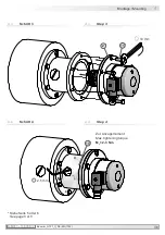
Страница 11: ...055617 Baumer_GTF7_II_DE EN 17A1 8 Montage Mounting 4 4 3 Schritt 3 4 3 Step 3 4 4 Schritt 4 4 4 Step 4 Siehe Seite 5 oder 6 See page 5 or 6 15 2 16 Zul Anzugsmoment Max tightening torque Mt 2 3 Nm 10 mm 2 5 mm ...

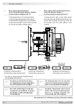
Страница 12: ...to the shaft without axial loading Zulässiger Parallelversatz Admissible parallel misalignment Zulässiger Winkelfehler Admissible angular error Zulässige Axialbewegung Admissible axial movement All dimensions in millimeters unless otherwise stated 0 2 0 05 1 Für Version mit isolierender Kunststoffnabe For insulated hub version 0 7 0 3 Der Anbau an den Antrieb muss mit möglichst geringem Winkelfeh ...

Страница 13: ...e carbon brushes 6 5 7 4 TX 10 17 mm Wir empfehlen den Tachogenerator so zu montieren dass der Kabelan schluss keinem direkten Was sereintritt ausgesetzt ist i i It is recommended to mount the ta chogenerator with cable connection facing downward and being not ex posed to water 17 Ansicht X siehe Abschnitt 6 1 View X see section 6 1 ø5 9 mm Zur Gewährleistung der angege benen Schutzart sind nur ge...

Страница 14: ... Abmessung Elektrischer Anschluss Dimension Electrical connection 6 Elektrischer Anschluss 6 1 Belegung Anschlussklemmen Polarität bei positiver Drehrichtung siehe Abschnitt 5 6 Electrical connection 6 1 Connecting terminal assignment Polarity at positive rotating direction see section 5 Ansicht X Anschlussklemmen siehe Abschnitt 4 6 View X Connecting terminal see section 4 6 Passfeder je nach Bes...

Страница 15: ...Betrieb gewährleistet ist 7 Operation and maintenance 7 1 Replace of the carbon brushes When the minimum brush length L of 5 5 mm is reached the brushes should be replaced and the commutator area should be cleaned with dry compressed air in or der to ensure perfect operation 13 12 13 4 Stück Kohlebürsten als Zubehör erhältlich Bestellnummer 11075833 H 87 13 4 pieces carbon brushes available as acc...

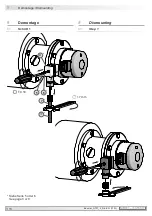
Страница 16: ... 13 Baumer_GTF7_II_DE EN 17A1 MB011 11055617 8 Demontage Dismounting 8 Demontage 8 1 Schritt 1 8 Dismounting 8 1 Step 1 Siehe Seite 5 oder 6 See page 5 or 6 6 5 7 4 17 TX 10 17 mm ...

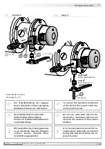
Страница 17: ...11055617 Baumer_GTF7_II_DE EN 17A1 14 Demontage Dismounting 8 8 2 Schritt 2 8 2 Step 2 8 3 Schritt 3 8 4 Schritt 4 8 3 Step 3 8 4 Step 4 Siehe Seite 5 oder 6 See page 5 or 6 16 14 2 15 16 10 mm 2 5 mm 2 5 mm ...

Страница 18: ...6 3 2007 A1 2011 GTF 7 08 Leistung 0 3 W Drehzahl 5000 U min GTF 7 16 Leistung 0 6 W Drehzahl 5000 U min 9 2 Technische Daten mechanisch Baugröße Flansch ø115 mm Wellenart ø11 mm Vollwelle Flansch EURO Flansch B10 Schutzart DIN EN 60529 IP55 Drehmoment 1 5 Ncm Zulässige Wellenbelastung 100 N axial 200 N radial Werkstoffe Gehäuse Edelstahl Kunststoff Welle Edelstahl Betriebstemperatur 30 130 C Wide...

Страница 19: ... 20 C Ω LA mH GTF7 08L 410 10 5 12 27 9000 60 20 GTF7 08L 420 20 20 48 108 9000 230 80 GTF7 08L 430 30 45 108 243 9000 550 180 GTF7 16L 440 40 40 96 216 9000 410 160 GTF7 16L 460 60 90 215 223 6100 760 360 Überlagerte Welligkeit für τRC 0 3 ms 0 6 Spitze Spitze 0 25 effektiv 9 3 Daten nach Typ 9 4 Ersatzschaltbild RA LA U0 n U n RL 2A1 R 2A2 GTF 7 C U n U0 n RL U0 n RA RL τRC R C τA LA RL für R RL...

Страница 20: ... 2007 A1 2011 GTF 7 08 Performance 0 3 W speed 5000 rpm GTF 7 16 Performance 0 6 W speed 5000 rpm 9 2 Technical data mechanical design Size flange ø115 mm Shaft type ø11 mm solid shaft Flange EURO flange B10 Protection DIN EN 60529 IP55 Torque 1 5 Ncm Shaft loading 100 N axial 200 N radial Materials Housing stainless steel plastic Shaft stainless steel Operating temperature 30 130 C Resistance IEC...

Страница 21: ...re inductance 0 3000 0 6000 0 nmax U0 mV rpm RL kΩ RL kΩ RL kΩ nmax rpm RA 20 C Ω LA mH GTF7 08L 410 10 5 12 27 9000 60 20 GTF7 08L 420 20 20 48 108 9000 230 80 GTF7 08L 430 30 45 108 243 9000 550 180 GTF7 16L 440 40 40 96 216 9000 410 160 GTF7 16L 460 60 90 215 223 6100 760 360 Superimposed ripple for τRC 0 3 ms 0 6 peak peak 0 25 rms 9 3 Data according to type 9 4 Replacement switching diagram P...

Страница 22: ...Accessories Spring disk coupling K 35 Carbon brushes see table in section 7 Tool kit order number 11068265 10 Zubehör Federscheiben Kupplung K 35 Kohlebürsten siehe Tabelle in Abschnitt 7 Werkzeugset Bestellnummer 11068265 16 13 16 13 Siehe Abschnitt 3 See section 3 18 18 ...

Страница 23: ...MB011 11055617 Baumer_GTF7_II_DE EN 17A1 ...

Страница 24: ...sprache der Anleitung ist Deutsch Technische Änderungen vorbehalten Original language of this instruction is German Technical modifications reserved Baumer Hübner GmbH P O Box 12 69 43 10609 Berlin Germany Phone 49 0 30 69003 0 Fax 49 0 30 69003 104 info baumerhuebner com www baumer com motion ...

Отзывы: