background image

MB097.1T1 - 11055707

  Baumer_HMG11-FSL-T1_II_DE-EN (16A2)   


46


8

8.4


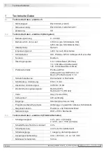
Technical data - mechanical design  

• 

Size (flange): 

ø122 mm

• 

Shaft type: 

ø16...20 mm (blind hollow shaft)


ø17 mm (cone shaft 1:10)

• 

Shaft loading: 

≤250 N axial


≤400 N radial

• 

Protection DIN EN 60529: 

IP 67

• 

Speed (n): 

≤1.25 · ns

• 

Range of switching speed (n

s

): 

850...2800 rpm (Δn = 2 rpm/s)

• 

Operating torque typ.: 

15 Ncm

• 

Rotor moment of inertia: 

790 gcm

2

• 

Materials: 

Housing: aluminium alloy


Shaft: stainless steel

• 

Operating temperature: 

-20...+85 °C

• 

Resistance: 

IEC 60068-2-6:2007


Vibration 5 g, 10-2000 Hz


IEC 60068-2-27:2008


Shock 50 g, 11 ms

• 

Connection: 

Bus cover


Terminal box or flange connector M23, 12-pin


(SSI/incremental)


Terminal box (FSL)

• 

Weight approx.: 

3.5 kg (depending on version)

9.5


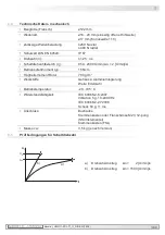
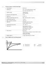
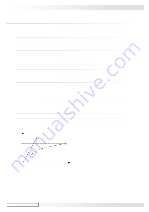
Test conditions for switching speed  

a)  Speed rise 

Δn = 

2 rpm/s

b)  Speed rise 

Δn =  1500 rpm/s

n

t

n

s

´

n

s

a)

b)

Содержание HMG 11 + FSL

Страница 1: ...mer_HMG11 FSL T1_II_DE EN 16A2 Montage und Betriebsanleitung Installation and operating instructions HMG 11 FSL Kombination Drehgeber mit integriertem Fliehkraftschalter Combination Encoder with integrated centrifugal switch ...

Страница 2: ...Nopen DeviceNet 21 5 4 Redundante Version SSI Inkremental 22 5 5 Redundante Version Profibus CANopen DeviceNet und SSI Inkremental 23 6 Elektrischer Anschluss 24 6 1 Profibus DP V0 24 6 1 1 Kabelanschluss 24 6 1 2 Klemmenbelegung und Schalterstellung 25 6 1 3 Funktionen 26 6 2 CANopen 27 6 2 1 Kabelanschluss 27 6 2 2 Klemmenbelegung und Schalterstellung 28 6 2 3 Funktionen 29 6 3 DeviceNet 30 6 3 ...

Страница 3: ... SSI incremental 22 5 5 Redundant version Profibus CANopen DeviceNet and SSI incremental 23 6 Electrical connection 24 6 1 Profibus DP V0 24 6 1 1 Cable connection 24 6 1 2 Terminal assignment and switch settings 25 6 1 3 Functions 26 6 2 CANopen 27 6 2 1 Cable connection 27 6 2 2 Terminal assignment and switch settings 28 6 2 3 Functions 29 6 3 DeviceNet 30 6 3 1 Cable connection 30 6 3 2 Termina...

Страница 4: ...en Kugellagern ab die mit einer Dauerschmierung ausgestattet sind 1 4 Der Lagertemperaturbereich des Gerätes liegt zwischen 15 C bis 70 C 1 5 Der Betriebstemperaturbereich des Gerätes liegt zwischen 20 C bis 85 C am Gehäuse gemessen 1 6 EU Konformitätserklärung gemäß den europäischen Richtlinien 1 7 Wir gewähren 2 Jahre Gewährleistung im Rahmen der Bedingungen des Zentralverbandes der Elektroindus...

Страница 5: ...etween 15 C and 70 C 1 5 The operating temperature range of the device is between 20 C and 85 C measured at the housing 1 6 EU Declaration of Conformity meeting to the European Directives 1 7 We grant a 2 year warranty in accordance with the regulations of the ZVEI Central Association of the German Electrical Industry 1 8 Maintenance work is not necessary Repair work must be carried out by the man...

Страница 6: ...unbedingt einhalten 2 4 Zerstörungsgefahr durch mechanischen Schock Starke Erschütterungen z B Hammerschläge können zur Zerstörung der Abtastung führen Niemals Gewalt anwenden Bei sachgemäßer Montage lässt sich alles leichtgängig zusam menfügen Für die Demontage geeignetes Abziehwerkzeug benutzen 2 5 Zerstörungsgefahr durch Verschmutzung Schmutz kann in der Kombination zu Kurzschlüssen und zur Bes...

Страница 7: ...ified clearances and or angles are observed 2 4 Risk of destruction due to mechanical shock Violent shocks e g due to hammer impacts can lead to the destruction of the optical sensing system Never use force Assembly is simple when correct procedure is followed Use suitable puller for disassembly 2 5 Risk of destruction due to contamination Dirt penetrating inside the combination can cause short ci...

Страница 8: ...ubung M20x1 5 für Kabel ø5 13 mm 1 Housing encoder HMG 11 2 Blind hollow shaft with spanner flat 13 a f 3 Clamping element 4 Torque sheet 5 Hexagon screw M6x18 mm ISO 4017 A2 10 mm a f 6 Washer B6 4 ISO 7090 A2 7 Self locking nut M6 ISO 10511 A2 10 mm a f 8 Earthing strap length 230 mm 9 D SUB connector male on the encoder housing 9 Second D SUB connector male depending on the version on the encod...

Страница 9: ...able gland M16x1 5 for cable ø5 9 mm 18 CANopen Haube 18a Kombi Torx Schraube M4x32 mm A2 18b Scheibe A4 DIN 137 A2 18c Buchse D SUB 9 polig zum Anschluss an Stecker D SUB 9 polig am Drehgebergehäuse 18d Anschlussklemmen siehe Abschnitt 6 2 2 18e Kabelverschraubung M16x1 5 für Kabel ø5 9 mm 18 CANopen cover 18a Screw with torx and slotted drive M4x32 mm A2 18b Washer A4 DIN 137 A2 18c Connector D ...

Страница 10: ...Buchse D SUB 9 polig zum Anschluss an Stecker D SUB 9 polig am Drehgebergehäuse 19d Anschlussklemmen siehe Abschnitt 6 3 2 19e Kabelverschraubung M16x1 5 für Kabel ø5 9 mm 19 DeviceNet cover 19a Screw with torx and slotted drive M4x32 mm A2 19b Washer A4 DIN 137 A2 19c Connector D SUB female 9 pin for connec tion to the connector D SUB male 9 pin on the encoder housing 19d Connecting terminal see ...

Страница 11: ...schlussklemmen siehe Abschnitt 6 4 1 2 20e Kabelverschraubung M20x1 5 für Kabel ø5 13 mm siehe Abschnitt 6 4 1 21 SSI Haube 21a Kombi Torx Schraube M4x32 mm A2 21b Scheibe A4 DIN 137 A2 21c Flanschdose M23 12 polig siehe Abschnitt 6 4 2 21d Rundsteckverbinder siehe Abschnitt 6 4 2 20 SSI cover 20a Screw with torx and slotted drive M4x32 mm A2 20b Washer A4 DIN 137 A2 20c Connector D SUB female 15 ...

Страница 12: ...ontageset als Zubehör erhältlich Bestellnummer 11077087 bestehend aus 26a Federring 6 DIN 7980 26b Zylinderschraube M6x30 ISO 4762 A2 22 Torque arm available as accessory order number length L version 11043628 67 70 mm standard 11004078 125 5 mm standard can be shortened to 71 mm 11002915 440 20 15 mm standard can be shortened to 131 mm 11054917 67 70 mm insulated 11072795 125 5 mm insulated can b...

Страница 13: ...mer 11077087 bestehend aus 26c Gewindestift M6x10 ISO 7436 5 8 Vzk 26d Zylinderschraube M8x45 ISO 4762 A2 26 Mounting dismounting kit available as accessory order number 11077087 including 26c Setscrew M6x10 ISO 7436 5 8 Vzk 26d Cylinder screw M8x45 ISO 4762 A2 27 Werkzeugset als Zubehör erhältlich Bestellnummer 11068265 27 Tool kit available as accessory order number 11068265 5 und 6 mm 1 6x8 0 m...

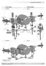
Страница 14: ...16A2 MB097 1T1 11055707 4 Montage Mounting 4 Montage 4 1 Schritt 1 4 Mounting 4 1 Step 1 4 2 Schritt 2 4 2 Step 2 10 mm 10 mm 7 4 6 5 21 11 10 Zul Anzugsmoment Max tightening torque Mt 2 3 Nm TX 20 Siehe Seite 5 oder 9 See page 5 or 9 ...

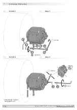
Страница 15: ...bination verkürzen können The drive shaft should have as less runout as possible because this can otherwise result in an angle error in the combination see section 4 8 In addition any radial deviation can cause vibrations which can shorten the lifetime of the combination M6 ødh6 L 16 mm 52 mm 40 52 mm 20 mm 34 mm 25 34 mm ø20 mm ød h6 L 53 mm 35 mm bei at ød 20 mm 16 mm 3 2 Siehe Seite 5 See page ...

Страница 16: ... Kombination zu einem Winkelfehler führen kann sie he Abschnitt 4 8 Außerdem verursa chen Rundlauffehler Vibrationen die die Lebensdauer der Kombination verkürzen können The drive shaft should have as less runout as possible because this can otherwise result in an angle error in the combination see section 4 8 In addition any radial deviation can cause vibrations which can shorten the lifetime of ...

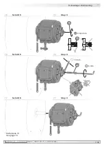
Страница 17: ...26b 5 mm 13 mm 25b 25b 22 21b 25c 25a 22 25b 25c 25d 25e 1 6x8 mm 8 10 mm Siehe Seite 5 oder 9 See page 5 or 9 Zul Anzugsmoment bei Version mit einseitig offener Hohlwelle Max tightening torque for blind hollow shaft version Mt 6 Nm Zul Anzugsmoment bei Version mit Konuswelle Max tightening torque for cone shaft version Mt 3 4 Nm ...

Страница 18: ...tze sollte spielfrei erfolgen Ein Spiel von beispiels weise 0 03 mm entspricht einem Rund lauffehler der Kombination von 0 06 mm was zu einem großen Winkelfehler führen kann siehe Abschnitt 4 8 The torque arm should be mounted free from clearance A play of just 0 03 mm results in concentricity error of the combination of 0 06 mm That may lead to a large angle error see section 4 8 ...

Страница 19: ...ene Befes tigungsbleche für die Stützen erhältlich 2 wenn L2 L1 muss mit der Länge L2 gerechnet werden Weitere Informationen erhalten Sie unter der Telefon Hotline 49 0 30 69003 111 i 4 8 How to prevent measurement errors Toensurethatthecombinationoperatescor rectly it is necessary to mount it accurately as described in section 4 1 to 4 7 which in cludes correct mounting of the torque arm The radi...

Страница 20: ..._DE EN 16A2 MB097 1T1 11055707 4 Montage Mounting 4 9 Schritt 7 4 9 Step 7 Ansicht B View B Zul Anzugsmoment Max tightening torque Mt 2 3 Nm TX 20 11 10 Siehe Seite 5 See page 5 Ansicht B Schieberstellung View B Slider position ...

Страница 21: ...4 10 Anbauhinweis 4 10 Mounting instruction Wir empfehlen die Kombination so zu montieren dass der Kabelanschluss keinem direkten Wassereintritt aus gesetzt ist i i It is recommended to mount the combination with cable connection facing downward and being not expo sed to water ...

Страница 22: ...imensions 5 1 Basic version Profibus CANopen DeviceNet 5 1 1 Blind hollow shaft 74366 5 1 2 Cone shaft All dimensions in millimeters unless otherwise stated Positive Drehrichtung Positive rotating direction Positive Drehrichtung Positive rotating direction Um 90 versetzt gezeichnet Drawing 90 rotated Um 90 versetzt gezeichnet Drawing 90 rotated ødH7 L1 L2 16 53 68 20 35 50 Zubehör Accessory Zubehö...

Страница 23: ...direction Um 90 versetzt gezeichnet Drawing 90 rotated Um 90 versetzt gezeichnet Drawing 90 rotated ødH7 L1 L2 16 53 68 20 35 50 5 2 Standardversion SSI Inkremental 5 2 1 Einseitig offene Hohlwelle 5 2 2 Konuswelle 5 2 Basic version SSI incremental 5 2 1 Blind hollow shaft 5 2 2 Cone shaft All dimensions in millimeters unless otherwise stated Zubehör Accessory Zubehör Accessory 13 13 ...

Страница 24: ...welle 5 3 2 Konuswelle 5 3 Redundant version Profibus CANopen DeviceNet 5 3 1 Blind hollow shaft 5 3 2 Cone shaft All dimensions in millimeters unless otherwise stated Positive Drehrichtung Positive rotating direction Positive Drehrichtung Positive rotating direction Um 90 versetzt gezeichnet Drawing 90 rotated Um 90 versetzt gezeichnet Drawing 90 rotated ødH7 L1 L2 16 53 68 20 35 50 Zubehör acces...

Страница 25: ...ction Um 90 versetzt gezeichnet Drawing 90 rotated Um 90 versetzt gezeichnet Drawing 90 rotated ødH7 L1 L2 16 53 68 20 35 50 5 4 Redundante Version SSI Inkremental 5 4 1 Einseitig offene Hohlwelle 5 4 2 Konuswelle 5 4 Redundant version SSI incremental 5 4 1 Blind hollow shaft 5 4 2 Cone shaft All dimensions in millimeters unless otherwise stated Zubehör Accessory 13 Zubehör Accessory 13 ...

Страница 26: ...5 5 2 Konuswelle 74345 5 5 Redundant version Profibus CANopen DeviceNet and SSI incremental 5 5 1 Blind hollow shaft 74370 74378 74380 5 5 2 Cone shaft 74345 All dimensions in millimeters unless otherwise stated Um 90 versetzt gezeichnet Drawing 90 rotated Um 90 versetzt gezeichnet Drawing 90 rotated ødH7 L1 L2 16 53 68 20 35 50 Positive Drehrichtung Positive rotating direction Positive Drehrichtu...

Страница 27: ...connection Ansicht U siehe Abschnitt 6 1 2 View U see section 6 1 2 17a 17b 17 17e 17d 17c 23 ø5 9 mm 50 mm Zul Anzugsmoment Max tightening torque Mt 2 3 Nm Kabelschirm Cable shield Siehe Seite 5 6 oder 9 See page 5 6 or 9 Zur Gewährleistung der angege benen Schutzart sind nur geeignete Kabeldurchmesser zu verwenden To ensure the specified protection of the device the correct cable dia meter must ...

Страница 28: ...eilnehmer Last user OFF Teilnehmer xx User xx Adresse über Drehschalter einstellbar Beispiel Teilnehmeradresse 23 Address can be set by rotary switch Example User address 23 a Settings for the terminating resistors b Einstellungen der Teilnehmeradresse b Settings for the user address A Negative serial data transmis sion pair 1 and pair 2 Terminals with the same label are internally connected B Pos...

Страница 29: ...flösung parametriert wer den Diagnose Der Drehgeber unterstützt folgende Fehlermeldungen Positionsfehler Defaulteinstellung Teilnehmeradresse 00 6 1 3 Funktionen 6 1 3 Functions Bus Protokoll Profibus DP V0 Profibus Features Device Class 1 und 2 Data exch functions Input Position value Output Preset value Preset value The Preset parameter can be used to set the encoder to a predefined value that c...

Страница 30: ...s 6 2 CANopen 6 2 1 Cable connection Zur Gewährleistung der angegebenen Schutzart sind nur geeignete Kabel durchmesser zu verwenden To ensure the specified protection of the device the correct cable diameter must be used 18d 18c 23 ø5 9 mm 50 mm Kabelschirm Cable shield Siehe Seite 5 6 oder 9 See page 5 6 or 9 18a 18b 18 18e Zul Anzugsmoment Max tightening torque Mt 2 3 Nm TX 20 17 mm 18c 9 ...

Страница 31: ... user OFF Teilnehmer xx User xx Adresse über Drehschalter einstellbar Beispiel Teilnehmeradresse 23 Address can be set by rotary switch Example User address 23 a Settings for the terminating resistors b Einstellungen der Teilnehmeradresse b Settings for the user address CAN_L CAN Bus signal dominant low Terminals with the same label are internally connected CAN_H CAN Bus signal dominant high UB Vo...

Страница 32: ...frage asynchron mit SDO Zyklisch asynchon zyklisch Synchron synchron zyklisch Azyklisch synchron azyklisch Diagnose Der Drehgeber unterstützt folgende Fehlermeldungen Positionsfehler Defaulteinstellung Teilnehmeradresse 00 6 2 3 Funktionen 6 2 3 Functions Bus Protokoll CANopen CANopen features Device Class 2 CAN 2 0B Device profile CANopen CiA DSP 406 V 3 0 Operation modes Polling mode asynch via ...

Страница 33: ... der angegebenen Schutzart sind nur geeignete Kabel durchmesser zu verwenden To ensure the specified protection of the device the correct cable diameter must be used Ansicht W siehe Abschnitt 6 3 2 View W see section 6 3 2 19d 19c 23 ø5 9 mm 50 mm Kabelschirm Cable shield Siehe Seite 5 7 oder 9 See page 5 7 or 9 19a 19b 19 19e Zul Anzugsmoment Max tightening torque Mt 2 3 Nm TX 20 17 mm 19c 9 ...

Страница 34: ... OFF Teilnehmer xx User xx Adresse über Drehschalter einstellbar Beispiel Teilnehmeradresse 23 Address can be set by rotary switch Example User address 23 a Settings for the terminating resistors b Einstellungen der Teilnehmeradresse b Settings for the user address CAN_L CAN Bus signal dominant low Terminals with the same label are internally connected CAN_H CAN Bus signal dominant high DRAIN Shie...

Страница 35: ... hung und Gesamtauflösung parametriert werden Diagnose Der Drehgeber unterstützt folgende Fehlermeldungen Positions und Parameterfehler Defaultein stellung Teilnehmeradresse 00 6 3 3 Funktionen 6 3 3 Functions Bus Protokoll DeviceNet Features Device Profl for Encoders V 1 0 Operation modes I O Polling Cyclic Change of State Preset value The Preset parameter can be used to set the encoder to a pred...

Страница 36: ...6 4 1 1 Cable connection 20b 20 20a 20e 20d 20c 23 ø5 13 mm 50 mm 9 20c Zul Anzugsmoment Max tightening torque Mt 2 3 Nm Kabelschirm Cable shield Siehe Seite 5 8 oder 9 See page 5 8 or 9 Zur Gewährleistung der angegebenen Schutzart sind nur geeignete Kabel durchmesser zu verwenden To ensure the specified protection of the device the correct cable diameter must be used Ansicht X siehe Abschnitt 6 4...

Страница 37: ...erversion stehen gegebenenfalls nicht alle Signale zur Verfügung Note depending on the version of the encoder not all signals may be available Betriebsspannung nicht auf Ausgän ge legen Zerstörungsgefahr Spannungsabfälle in langen Leitungen berücksichtigen Ein und Ausgänge Do not connect voltage supply to outputs Danger of damage Please beware of possible voltage drop in long cable leads inputs an...

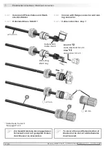
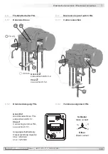
Страница 38: ...n 6 4 2 3 6 4 2 Version mit Flanschdose und Rund steckverbinder 6 4 2 1 Kabelanschluss Schritt 1 6 4 2 Version with flange connector and mat ing connector 6 4 2 1 Cable connection step 1 Zur Gewährleistung der angegebenen Schutzart sind nur geeignete Kabel durchmesser zu verwenden To ensure the specified protection of the device the correct cable diameter must be used 21d Siehe Seite 8 oder 9 See ...

Страница 39: ... 2 Ansicht Y2 Löteinsatz siehe Abschnitt 6 4 2 1 View Y2 Insert with solder contacts see section 6 4 2 1 Hinweis Je nach Drehgeberversion stehen gegebenenfalls nicht alle Signale zur Verfügung Note depending on the version of the encoder not all signals may be available 6 4 2 3 Belegung Flanschdose 6 4 2 3 Flange connector assignment 6 4 2 2 Kabelanschluss Schritt 2 6 4 2 2 Cable connection step 2...

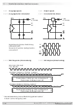
Страница 40: ...cremental line drivers HTL TTL 6 4 3 2 SSI Telegramm Voreinstellung 6 4 3 2 SSI telegram default setting Positionsdaten 13 Bit Gray Code rechtsdrehend Position data 13 Bit gray code CW LSB MSB 1 2 3 4 5 6 7 8 9 10 11 12 13 12µs 30µs SSI Clock SSI clock 100 800 kHz SSI Daten Singleturn SSI data singleturn SSI Daten Multiturn SSI data multiturn Positionsdaten 25 Bit Gray Code rechtsdrehend Position ...

Страница 41: ...Cable connection 6 5 2 Klemmenbelegung FSL 6 5 2 Terminal assignment FSL Ansicht Z siehe Abschnitt 6 5 2 View Z see section 6 5 2 14 13 15 16 24 22 mm TX 20 Ausgangsschaltleistung Output switching capacity 6 A 230 VAC 1 A 125 VDC 1 2 3 3 4 1 2 4 Schließer Make contact Öffner Break contact Ansicht Z Anschlussklemmen FSL siehe Abschnitt 6 5 1 View Z Connecting terminal FSL see section 6 5 1 ...

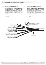
Страница 42: ...Data Data 6 6 Sensorkabel HEK 8 Zubehör Es wird empfohlen das Baumer Hübner Sensorkabel HEK 8 zu verwenden oder ersatzweise ein geschirmtes paarig ver seiltes Kabel Das Kabel sollte in einem Stück und getrennt von Motorkabeln ver legt werden Kabelabschluss 1 3 kΩ 6 6 Sensor cable HEK 8 accessory Baumer Hübner sensor cable HEK 8 is recommended As a substitute a shielded twisted pair cable should be...

Страница 43: ...N 16A2 40 Demontage Dismounting 7 17 mm 22 mm 22 mm TX 20 TX 20 TX 20 21 20 20e 17e 18e 19e 17 18 19 13 16 15 14 23 24 23 7 Demontage 7 1 Schritt 1 7 2 Schritt 2 7 Dismounting 7 1 Step 1 7 2 Step 2 Siehe Seite 5 bis 9 See page 5 up to 9 21c 21d 23 ...

Страница 44: ...MG11 FSL T1_II_DE EN 16A2 MB097 1T1 11055707 7 Demontage Dismounting 7 4 Schritt 4 7 4 Step 4 7 3 Schritt 3 7 3 Step 3 25a 22 25b 25c 25d 25e 1 6x8 mm 8 10 mm 26a 26b 5 mm 13 mm Siehe Seite 5 oder 9 See page 5 or 9 ...

Страница 45: ...1T1 11055707 Baumer_HMG11 FSL T1_II_DE EN 16A2 42 Demontage Dismounting 7 13 mm Siehe Seite 10 See page 10 7 5 Schritt 5 7 5 Step 5 7 6 Schritt 6 7 6 Step 6 26c 26d 0 8x4 mm 6 mm 7 7 Schritt 6 7 7 Step 6 26c ...

Страница 46: ...Profilkonformität Profibus DPV0 CANopen CiA DSP 406 V 3 0 Device Profile Encoder V 1 0 Teilnehmeradresse Drehschalter in Bushaube Schrittzahl je Umdrehung 8192 13 Bit Anzahl der Umdrehungen 65536 16 Bit Zusätzliche Ausgangssignale Rechteck HTL Rechteck TTL RS422 Code Gray Version SSI Codeverlauf CW werkseitig Eingänge SSI Takt bei Version SSI Programmierbare Parameter Abhängig von gewählter Absolu...

Страница 47: ...800 U min Δn 2 U min s Betriebsdrehmoment typ 15 Ncm Trägheitsmoment Rotor 790 gcm2 Werkstoffe Gehäuse Aluminiumlegierung Welle Edelstahl Betriebstemperatur 20 85 C Widerstandsfähigkeit IEC 60068 2 6 2007 Vibration 5 g 10 2000 Hz IEC 60068 2 27 2008 Schock 50 g 11 ms Anschluss Bushaube Klemmenkasten oder Flanschdose M23 12 polig SSI Inkremental Klemmenkasten FSL Masse ca 3 5 kg je nach Version 8 5...

Страница 48: ...e conformity Profibus DPV0 CANopen CiA DSP 406 V 3 0 Device Profile Encoder V 1 0 Device adress Rotary switch in bus cover Steps per turn 8192 13 bit Number of turns 65536 16 bit Additional output signals Square wave TTL RS422 Square wave HTL Code Gray version SSI Code sequence CW default Inputs SSI clock version SSI Programmable parameters Depending on the selected absolute interface Diagnostic f...

Страница 49: ...0 rpm Δn 2 rpm s Operating torque typ 15 Ncm Rotor moment of inertia 790 gcm2 Materials Housing aluminium alloy Shaft stainless steel Operating temperature 20 85 C Resistance IEC 60068 2 6 2007 Vibration 5 g 10 2000 Hz IEC 60068 2 27 2008 Shock 50 g 11 ms Connection Bus cover Terminal box or flange connector M23 12 pin SSI incremental Terminal box FSL Weight approx 3 5 kg depending on version 9 5 ...

Страница 50: ...tic links HEAG 172 HEAG 174 and HEAG 176 Digital speed switch DS 93 Analyzer for encoders HENQ 1100 9 Zubehör Drehmomentstütze Größe M6 Bestellnummer siehe Abschnitt 4 2 Sensorkabel für Drehgeber HEK 8 Montageset für Drehmomentstütze Größe M6 Bestellnummer 11077197 Montage und Demontageset Bestellnummer 11077087 Werkzeugset Bestellnummer 11068265 Digital Konverter HEAG 151 HEAG 152 und HEAG 154 LW...

Страница 51: ...MB097 1T1 11055707 Baumer_HMG11 FSL T1_II_DE EN 16A2 ...

Страница 52: ... Baumer Hübner GmbH P O Box 12 69 43 10609 Berlin Germany Phone 49 0 30 69003 0 Fax 49 0 30 69003 104 info baumerhuebner com www baumer com motion Originalsprache der Anleitung ist Deutsch Technische Änderungen vorbehalten Original language of this instruction is German Technical modifications reserved ...

Отзывы: