background image


29 


* Press the Enter key to save changes.   
 

4.3.3.10 Turn off the Utility Input breaker. 
4.3.3.11 Your setting changes are now complete. 


4.3.3.12 Turn UPS off 

(1) 

Line mode(AC input available) : Press Off key


and hold until twice 

beeps heard, UPS output will shut off.    UPS will stay in standby mode, 
fan(s) keep spinning and battery will be remained recharging if AC input 
still available after output is off, otherwise it will be shutdown completely.   

(2) 

Backup mode (AC input not available): Press Off key

  and hold until 

twice beeps heard, UPS output will shut off.    10 seconds later, fan stop 
spinning and UPS shutdown completely. 


4.3.3.13 Self-Test (Line mode only) 

The purpose of self-test is to ensure the backup capability of battery set 
and it can only be applied when UPS is working under line mode (AC 
input available) and battery set was proper recharged. 

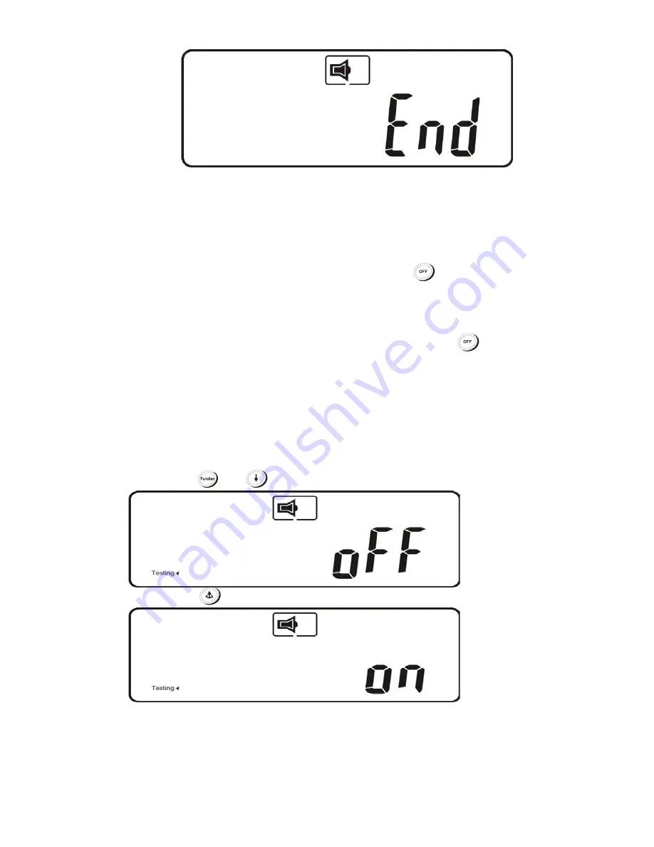
Press key 


  to change the LCD display to below figure. 


And press 

  key to start self-test as below figure. 


If UPS transfer to backup mode for 10sec and transfer back to line mode 
operation without any code or alarm, means the battery set is healthy, 
otherwise UPS may give code to indicate the cause of failure. 


Содержание BBP-AR-1000-PSW-ONL

Страница 1: ...1 1 5 2 and 3 kVA Intelligent True On Line UPS For Corporate and IT Users User Manual ...

Страница 2: ...planation 14 4 Installation and Operation 15 4 1 Unpacking 15 4 2 Selecting Installation Position 16 4 3 Operation 17 5 UPS System Block Diagram 31 6 Maintenance Guide 32 6 1 Troubleshooting 32 6 2 Error Codes and Their Meanings 35 6 3 Maintenance 35 7 Communication Software 36 7 1 Hardware Setup 36 7 2 Software Installation 36 8 Optional Communication Cards 37 8 1 R2E second RS 232 card 37 8 2 US...

Страница 3: ...le check that the ground wire of the UPS is properly grounded before connecting the UPS to the AC mains 6 This UPS is designed to be installed and commissioned in a sheltered controlled environment as follows Ensure that the UPS is installed within the proper environmental range 0 40 C and 0 90 non condensing humidity High ambient temperature reduces battery life Do not install the UPS in direct s...

Страница 4: ...ls 16 Make sure that the AC utility outlet is correctly grounded 17 Install the UPS away from objects that give off excessive heat and areas that are excessively wet 18 The battery will discharge naturally if the system is unused for a long time 19 This UPS supports electronic equipment in office telecommunication process control medical and security applications Non authorized technicians are not...

Страница 5: ...ical shock and high short circuit current The following precautions should be observed when working on batteries 1 Remove watches rings or other metal objects 2 Use tools with insulated handles 3 Wear rubber gloves and boots 4 Do not lay tools or metal parts on top of batteries 5 Disconnect charging source prior to connecting or disconnecting battery terminals 6 Determine if battery is inadvertent...

Страница 6: ... stored in a moderate climate The batteries should be charged for 12 hours every three months by connecting the UPS to the utility supply and switching on the input breaker located on the UPS rear panel Repeat this procedure every two months if the storage ambient temperature is above 25 C ...

Страница 7: ... friendly plug and play design allows hassle free installation 5 Built in maintenance free sealed batteries minimize the need for after sales service 6 To protect the unit from overloading the UPS will automatically switch to bypass mode in 30 seconds if loading is at 105 of rated capacity It will automatically switch back to inverter mode once the overload condition ceases 7 Should the output bec...

Страница 8: ...even during power outages 5 Our smart battery management system extends the batteries life span 6 Our Active Power Factor Correction control function constantly maintains the UPS input power factor at 0 98 for superb energy efficiency 7 Our Selectable Bypass input voltage tolerance sensitivity low high prevents under or over voltage being supplied to the loads in Bypass mode The selectable voltage...

Страница 9: ...ond OFF UPS Power Off Switch Press and hold until the buzzer beeps Self Test a Commands the UPS to perform self testing Press and hold until the buzzer beeps b Battery and Load Display Function Mode Do not hold for 1 second Manual Bypass Press the ON key and Self Test key simultaneously for three seconds to transfer from Inverter to Bypass The bypass LED will continuously blink and the buzzer will...

Страница 10: ...d LED 1 Indicates UPS is overloaded 2 In Error Code Function Mode indicates Error Code 16 Site wiring fault LED 1 Indicates live and neutral lines are connected wrongly or high neutral ground voltage 2 In Battery and Load Function Mode indicates load capacity is 100 3 In Error Code Function Mode indicates Error Code 8 Outlet1 LED 1 Indicates UPS Outlets 1 are enabled and ready to supply loads This...

Страница 11: ...tage is within the window In standby mode 90Vac 150Vac In Line mode 55Vac 150Vac Green LED lights up to indicate there is an output available at the Programmable Outlet 1 Programmable Outlet 2 Amber LED lights up to indicate the Bypass Input is normal UPS Fault LED UPS On Alarm Silence UPS OFF Switch Special functions log in out Go to next page ...

Страница 12: ...S Setting Manual Bypass press ON KEY and Up KEY key simultaneously for approx 3 seconds to transfer from Inverter to Bypass the bypass led continuously blink and the buzzer will beep intermediately or Bypass to Inverter when the UPS is on Line Mode and the Bypass Voltage Window is Normal ...

Страница 13: ...bypass Bypass Abnormal at ECO mode 2 Utility Input Abnormal 3 Site Wiring Fault 4 Buzzer Silent 5 UPS Overloading 6 UPS Working in specified mode 7 UPS Fault or Abnormal Warning 8 UPS Flow Chart 9 3 Digit Measurement Display 10 Indicates the item to be measured 11 Battery Abnormal 12 Battery Low 13 Testing ...

Страница 14: ...B port 3 RS 232 port 4 Fan 5 External battery connector 6 Slot for optional communication cards 7 AC power connection socket 8 Utility input circuit breaker 9 Output circuit breaker for two outlets 10 AC outlets Program Relay 11 Communication surge protection Remark Optional function 1K 1 5K 2K 3K ...

Страница 15: ...contact your local dealer for suitable software All communication ports including optional cards can be active and used simultaneously to monitor the UPS status However only one communication interface at a time the one with the highest priority can control the UPS The priorities of these communication interfaces are as follows highest priority first 1 EPO ROO input port 2 Optional interface card ...

Страница 16: ...damage may still occur during shipment Notify the forwarder and dealer if there is damage The packaging is recyclable and reusable 1 After removing the packing foam please be careful handling the UPS while it is still in the plastic bag The plastic is slippery and the UPS could fall and injure your feet 2 Check for the following standard package contents in addition to the UPS itself A User Manual...

Страница 17: ...ments 1 Keep at least 20 cm 8 inches of clearance beyond the rear panel of the UPS 2 Do not block the air flow to the ventilation louvers of the unit 3 Ensure that the installation site is free from excessive dust and the ambient temperature and humidity are within the specified limits 4 Do not place the UPS in a dusty or corrosive environment or near any flammable objects 5 This UPS is not design...

Страница 18: ...e loads to the UPS to ensure that the batteries are working properly To do this switch off the AC power source when the UPS is on The LED on the front panel display will turn off the LED will shine and the buzzer will pulsate indicating that the UPS is in Battery Mode Connect a non critical load to the UPS outlets to confirm that the batteries are supplying power Repeat the test by switching on an...

Страница 19: ... to the outlets The LEDs will turn off and the ventilating fans will stop after ten seconds and the BUS discharge is below 42 V The UPS is now completely shut down 4 3 1 4 Self Testing in AC Mode After the UPS has been successfully started in AC mode press and hold the Self Test button for five seconds until the buzzer beeps The LED will shine to indicate that the self test is in progress When the...

Страница 20: ...spinning Full LCD display looks as below figure 5 Press UPS button and hold untill twice beep heard UPS begins starting procedures for 5 seconds LCD display will show as below figure A and then figure B sequentially LEDs will light up to indicate that the Utility and the Bypass are normal And then LED remain lit during figure B LCD display A B When you see figure B means the starting up procedure ...

Страница 21: ...ailable or external battery set well connected to UPS Press and hold key for 3 seconds until twice beeps heard release button and press for 3 seconds until twice beeps heard again to confirm cold start procedure If the 2nd button confirmation not be finished within 10 seconds after 1st twice beeps UPS will not cold start and shut off after 10 seconds 2 5 seconds after cold starting amber LED will ...

Страница 22: ...sing select key The display sequence are as below figure F AC input voltage figure G AC input frequency figure H UPS output voltage figure I UPS output frequency figure J UPS loading percentage figure K UPS output current figure L Battery voltage figure M UPS inner temperature and back to figure F F G H I ...

Страница 23: ...22 J K L M ...

Страница 24: ...uzzer Code The procedures to release UPS from locked up status are as below a Check and record the error code b Check user s manual to understand possible cause solve the problem or call service provider c Press OFF key and hold for 5 seconds until twice beep heard d Unplug AC input power cord or turn off power source switch e After UPS completely shut off UPS is unlocked ...

Страница 25: ...key to scroll through the UPS settings The LCD will display in sequence figure Q1 buzzer figure R1 Self test figure S1 Bypass Voltage Windows figure T Output Frequency Synchronization Window figure U Inverter Output Voltage figure V1 UPS Operation Mode figure W Output Voltage Micro Tune Value figure X UPS Id figure Y Parallel function status R1 Self test is not On R2 Self test is On ...

Страница 26: ...25 S1 Bypass Voltage is adjusted to wide range S2 Bypass Voltage is adjusted to narrow range T Frequency Window is 3 Hz U inverter output voltage ...

Страница 27: ...26 V1 The UPS is operating in normal mode ...

Страница 28: ...W Output Voltage Adjustment 3 2 1 0 1 2 3 4 3 2 6 Press the scroll up key to execute special functions The functions include buzzer ON as in figure Q1 buzzer OFF as in figure Q2 Alarm silence for UPS Warning and self test OFF as in figure R1 or self test ON as in figure R2 The UPS will execute the battery test for ten seconds ...

Страница 29: ...ass input acceptable window It follows the inverter output voltage Please refer specification for the detail 4 3 3 5 Figure T indicates the bypass frequency window of the Inverter Output The acceptable setting values are 3 Hz and 1 Hz 4 3 3 6 Figure U indicates the acceptable Inverter Output Voltage Possible values are 100 110 115 or 120 VAC 4 3 3 7 Figures V1 V2 V3 and V4 indicate the operation m...

Страница 30: ...able Press Off key and hold until twice beeps heard UPS output will shut off 10 seconds later fan stop spinning and UPS shutdown completely 4 3 3 13 Self Test Line mode only The purpose of self test is to ensure the backup capability of battery set and it can only be applied when UPS is working under line mode AC input available and battery set was proper recharged Press key to change the LCD disp...

Страница 31: ...s inhibited Long Continuous Beep Control keypad error Long Continuous Beep UPS faulty loads continue to be supplied via Inverter or Bypass Single beep every two seconds In battery mode Single beep once per second Battery low Quick and short successive beeps Confirm RS 232 port receiving two quick and short beeps Service mode okay one quick and short beep ...

Страница 32: ...ions Utility Condition UPS Operating Mode LEDs Normal Working power starts after approximately 5 seconds LEDs on the panel will blink and fans will start Press the ON button for 1 5 seconds The UPS starts up normally and LEDs remain lit Abnormal under or over voltage or absent Rectifier and charger stop operating Battery discharges via DC DC boost circuit and supplies Inverter Loads continue to re...

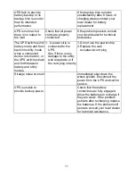
Страница 33: ... to provide DC backup Otherwise consult your local dealer right away 2 Overload 2 Disconnect some non critical loads from the UPS output until the overload ceases Check if there is any short circuit between cables due to broken cable insulation Replace the cables if necessary 3 Er11 UPS Over Temperature 3 Remove any objects obstructing the ventilation louvers Verify that the cooling fans are worki...

Страница 34: ...evice is turned on or the UPS switches back and forth between battery and utility modes 1 A power strip is connected to the UPS See if there is any damage to the utility wall receptacle or if the cord plug is faulty 1 Do not use the power strip 2 Replace the wall receptacle cord plug Strange noise or smell Immediately shut down the whole system Disconnect the power from the UPS and call for servic...

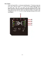
Страница 35: ... codes 1 2 4 8 and 16 are represented by the four bar LEDs 25 50 75 and 100 and the Overload LED Each LED represents a number as shown in the figure below For example the figure below shows the 25 50 and 100 bar LEDs lit The error code is therefore 8 2 1 11 or Er11 which indicates that the UPS is over temperature ...

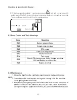
Страница 36: ... EPO mode Er11 UPS over temperature Er12 Inverter overload Er14 Fan errors Er39 When UPS start process Utility Voltage less than 90V and Battery no connection Er28 Bypass overload 6 3 Maintenance 1 Clean the dust from the ventilation openings and intakes on the rear panel 2 Turn off the UPS and wipe the casing with a damp cloth Be careful to avoid getting water in the UPS 3 Periodically unplug the...

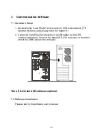
Страница 37: ...ional interface cards please refer to Chapter 8 2 Connect a male RS 232 connector or a USB cable to the UPS communication port Connect the female RS 232 connector or the other end of the USB cable to the computer Note RS 232 and USB cables are optional 7 2 Software Installation Please refer to the software user s manual ...

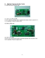
Страница 38: ...2 DB9 8 1 2 For interface settings and pin assignments please refer to section 3 3 1 8 1 3 Installation Position Optional Slot 8 2 USE USB card 8 2 1 CN1 is for USB 8 2 2 For the communicaiton protocol definition please refer to section 8 4 2 8 2 3 Installation Position Optional Slot ...

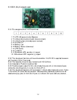
Страница 39: ...ctivated after 6 25 VDC is applied between pin 9 and pin 10 for 5 seconds 8 3 3 The capacity of each relay contact is 40 VDC 25 mA 8 3 4 Installation Position Optional Slot 8 3 5 Flexible signal output for N C Normally Closed or N O Normally Open contact by shorting pins1 2 or pins 2 3 from JP1 5 8 3 6 The shutdown function will be enabled 1 minute after blackout occurs if pins 1 2 of both CN1 and...

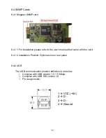
Страница 40: ...the user s manual that came with the card 8 4 1 2 Installation Position Optional slot on rear panel 8 4 2 USB The USB communication protocol definition is as below 1 Complies with USB version 1 0 1 5 Mbps 2 Complies with USB HID version 1 0 3 Pin Assignments 1 VCC 5V 2 D 3 D 4 Ground ...

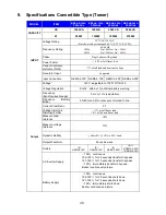
Страница 41: ...10 115 120 Voltage Regulation Static within 1 until low battery warning Frequency Synchronized Range 3 Hz or 1 Hz selectable Frequency Battery Mode 50 60 Hz 0 2 unless synchronized to line Current Crest Ratio 3 1 Voltage Harmonic Distortion THDv 3 at full linear load 6 at full non linear load Measure Load tolerance 2 Measure voltage tolerance 1 Dynamic stability 60ms 5 10 to 90 Load Output Wavefor...

Страница 42: ...ad 3 min 3 min 3 min 3min Charger Charge Current Max Standard 1 8 A 1 8 A 1 6A 1 4 A Supplementary Charger Max Optional 3 1A 3 1A 3 1A 3 1A Recharge time to 90 4hr 4hr 4hr 4hr Floating Mode Charging Voltage 27 3Vdc 1 40 95 dc 1 54 6Vdc 1 81 9Vdc 1 Bulk Mode Charging Voltage 28 2Vdc 1 42 3Vdc 1 56 4Vdc 1 84 6Vdc 1 DC leakage current 30 µA with no AC applied and the unit in the off position Transfer...

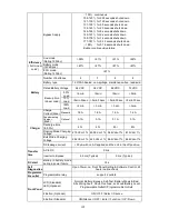
Страница 43: ...104ºF Storage 10ºC 50ºC 14ºF to 122ºF Noise Level 50dB Relative Humidity 0 90 without condensation Interface Standard RS 232 USB Port EPO ROO RJ11 RJ45 Surge Protection UPS Bundled UPSilon2000 Software Option 2ndRS 232 RS485 Dry Contact Closure Mega SNMP HTTP Agent Peripherals Only Compatible Platforms Microsoft Windows series Linux Mac etc Standards and Certificatio ns Safety UL1778 V4 cTUVus EMC...

Отзывы: