9252000892 Rev A
BE1-50/51B-229 Testing
5-1
SECTION 5
•
TESTING
INTRODUCTION
Proper relay operation may be confirmed by performing the test procedures of this section. When the
relay is not in service, it should be stored in its original carton in a dry, dust-free environment.
DIELECTRIC TESTING
In accordance with IEC 255-5 and IEEE C37.90-1989, one-minute dielectric (high potential) tests may be
performed as follows.
All circuits to ground:
2828 Vdc
Input circuits to output circuits:
2000 Vac or 2828 Vdc
Output contacts are surge protected.
OPERATIONAL TESTING
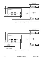
The following procedures verify operation of the BE1-50/51B-229 Overcurrent Protection Relay. The test
setups illustrated in Figures 5-1 and 5-2 are intended as an illustration of the principles involved. Other
test setups known to be capable of testing with the stated and implied tolerances (including equipment
specifically designed for testing relays) may be used.
Test Equipment Required
•
Current source, 0 to 20 Aac (for sensing input current)
•
Current source, 0.2 to 3 Aac (for target operation)
•
Timer or counter
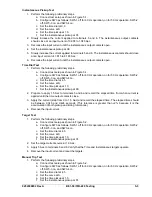
Time Pickup Test
1. Perform the following preliminary steps.
a. Connect test setup as shown in Figure 5-1.
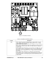
b. Configure SW3 as follows: SW3-1 off for 60 Hz operation, on for 50 Hz operation, SW3-2
off, SW3-3 on, and SW3-4 on.
c. Set the time dial at 0.0.
d. Set the curve at S.
e. Set the time pickup at 0.5.
f.
Set the instantaneous pickup at 90.
2. Slowly increase the current applied to terminals 5 and 6. The Active/Pickup LED should turn red
at a maximum input current of 0.55 Aac.
3. Decrease the input current until the Active/Pickup LED turns green, then off.
4. Set the time pickup at 2.2.
5. Slowly increase the current applied to terminals 5 and 6. The Active/Pickup LED should change
from green to red at an input current of 2.131 to 2.269 Aac.
6. Decrease the input current until the Active/Pickup LED turns off.
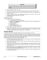
NOTE
To ensure proper timing, before each test, remove the current from the relay
for R times D seconds (refer to Section 1,
General Information, Specifications,
Integrating Time Reset Characteristic
for R and D definitions).
When testing time overcurrent functions, instantaneous pickup settings of 00
will also affect the calibration of the time functions. Time pickup settings of 00
will also affect instantaneous functions.
Содержание BE1-50/51B-229
Страница 1: ...INSTRUCTION MANUAL FOR OVERCURRENT RELAY BE1 50 51B 229 Publication 9252000892 Revision A 03 08 ...
Страница 2: ......
Страница 6: ...iv BE1 50 51B 229 Introduction 9252000892 Rev A This page intentionally left blank ...
Страница 8: ...vi BE1 50 51B 229 Introduction 9252000892 Rev A This page intentionally left blank ...
Страница 10: ...ii BE1 50 51B 229 General Information 9252000892 Rev A This page intentionally left blank ...
Страница 20: ...ii BE1 50 51B 229 Controls and Indicators 9252000892 Rev A This page intentionally left blank ...
Страница 24: ...2 4 BE1 50 51B 229 Controls and Indicators 9252000892 Rev A This page intentionally left blank ...
Страница 26: ...ii BE1 50 51B 229 Functional Description 9252000892 Rev A This page intentionally left blank ...
Страница 30: ...ii BE1 50 51B 229 Installation 9252000892 Rev A This page intentionally left blank ...
Страница 34: ...4 4 BE1 50 51B 229 Installation 9252000892 Rev A This page intentionally left blank ...
Страница 36: ...ii BE1 50 51B 229 Testing 9252000892 Rev A This page intentionally left blank ...
Страница 42: ...ii BE1 50 51B 229 Time Characteristic Curves 9252000892 Rev A This page intentionally left blank ...
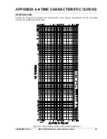
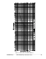
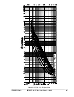
Страница 45: ...9252000892 Rev A BE1 50 51B 229 Time Characteristic Curves A 3 Figure A 3 D Definite Time Similar to ABB CO 6 ...
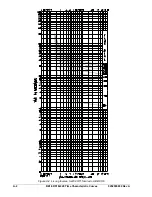
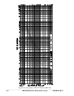
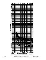
Страница 50: ...A 8 BE1 50 51B 229 Time Characteristic Curves 9252000892 Rev A Figure A 8 BS142 B Very Inverse ...
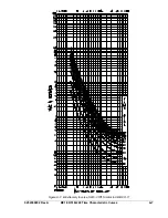
Страница 51: ...9252000892 Rev A BE1 50 51B 229 Time Characteristic Curves A 9 Figure A 9 BS142 C Extremely Inverse ...

