3-2
BE1-50/51B-229 Functional Description
9252000892 Rev A
operation, and turns off the Active/Pickup LED. The Microprocessor Watchdog feature resets the
Microprocessor when the flow of program code is interrupted.
The Microprocessor also receives information from the Time Dial Selector Switches (SW7 and SW8) and
the 50/60 Hz/Instantaneous Delay/Reset Characteristic/Curve Select Switch (SW3). These inputs are
used by the Microprocessor to set the operating parameters.
When the Microprocessor is ready to receive analog information from the Multiplexor, Microprocessor
control signals cause the Multiplexor to route the desired input through to the output. The output is
converted from an analog value to a digital value and applied to the Microprocessor.
The Microprocessor performs the program operations based on received inputs and the internal software
program. When the sensed current exceeds the setting of the Time Pickup Selector Switches (SW4 and
SW5), the Active/Pickup LED changes from green to red and the Time (51) output contacts close in
accordance with the time characteristic equation. If the sensed current exceeds the setting of the
Instantaneous Pickup Selector Switches (SW1 and SW2), the Instantaneous (50) output contacts close.
Power-Off Sensing
Power-Off Sensing circuitry measures the voltage across a capacitor at power-up and power-down. This
circuitry determines how long power has been absent based on the voltage difference and the circuit RC
time constant. This provides information for the Integrating Reset Function even when power has been
removed entirely.
Relay Outputs
Circuit breakers controlled by the relay can be tripped manually by applying a short-circuit across the
Time Manual Trip Test Jacks or Instantaneous Manual Trip Test Jacks. Current flow in the trip circuit is
indicated by the operation of the appropriate target indicator. The targets will not operate without
adequate operating power for the relay.
WARNING!
Trip circuit voltage is present at the front panel test jacks. When short-circuiting
the test jacks, use insulated jumpers to avoid contact with this voltage.
Содержание BE1-50/51B-229
Страница 1: ...INSTRUCTION MANUAL FOR OVERCURRENT RELAY BE1 50 51B 229 Publication 9252000892 Revision A 03 08 ...
Страница 2: ......
Страница 6: ...iv BE1 50 51B 229 Introduction 9252000892 Rev A This page intentionally left blank ...
Страница 8: ...vi BE1 50 51B 229 Introduction 9252000892 Rev A This page intentionally left blank ...
Страница 10: ...ii BE1 50 51B 229 General Information 9252000892 Rev A This page intentionally left blank ...
Страница 20: ...ii BE1 50 51B 229 Controls and Indicators 9252000892 Rev A This page intentionally left blank ...
Страница 24: ...2 4 BE1 50 51B 229 Controls and Indicators 9252000892 Rev A This page intentionally left blank ...
Страница 26: ...ii BE1 50 51B 229 Functional Description 9252000892 Rev A This page intentionally left blank ...
Страница 30: ...ii BE1 50 51B 229 Installation 9252000892 Rev A This page intentionally left blank ...
Страница 34: ...4 4 BE1 50 51B 229 Installation 9252000892 Rev A This page intentionally left blank ...
Страница 36: ...ii BE1 50 51B 229 Testing 9252000892 Rev A This page intentionally left blank ...
Страница 42: ...ii BE1 50 51B 229 Time Characteristic Curves 9252000892 Rev A This page intentionally left blank ...
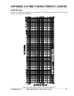
Страница 45: ...9252000892 Rev A BE1 50 51B 229 Time Characteristic Curves A 3 Figure A 3 D Definite Time Similar to ABB CO 6 ...
Страница 50: ...A 8 BE1 50 51B 229 Time Characteristic Curves 9252000892 Rev A Figure A 8 BS142 B Very Inverse ...
Страница 51: ...9252000892 Rev A BE1 50 51B 229 Time Characteristic Curves A 9 Figure A 9 BS142 C Extremely Inverse ...


