Bartec SDBX-Cat5-KVM-Extender Скачать руководство пользователя страница 7

Cat5 interconnect cable

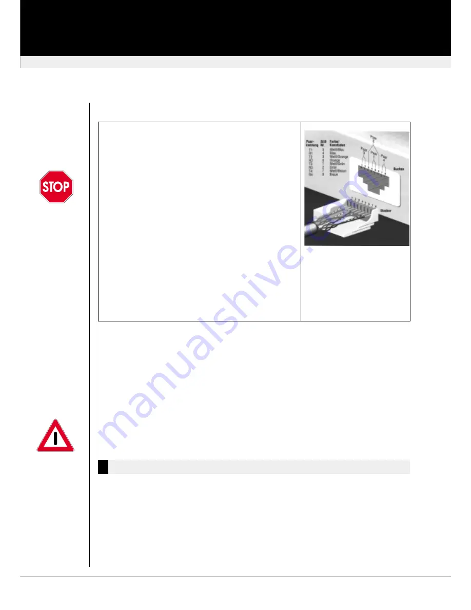
The Local and Remote Units are interconnected by industry

standard structured cabling (Category 5, Cat5e, Cat6, Cat7

UTP/STP, 4-pair) terminated with RJ45 connectors. This

cable is not supplied with the Extenders.

The cable used should be solid trunk cable

.

Stranded

patch cable will result in poor quality video.

Note:

That

failure to wire the twisted pairs correctly will impair the

video quality dramatically and / or prevent correct

operation.

The Mini Extender is designed for use up to a maximum

cable length of 300 Meters. At this length the video quality

should still be acceptable even at a screen resolution of

1280x1024 (75Hz).
Although a single continuous length of interconnect cable is

preferable, operation is possible through multiple patch

panels. However, the more patch panels the cable is routed

through, the greater the chance of video signal degradation.

Using other types of structured cabling

Although specified for Category 5 cabling, the Mini Extender

system has been tested on CAT 3 cable and on pairs within

a 25-pair UTP trunk cable.

SDBX/S1, SDBX/SA1, SDBX/D1 and SDBX/DA1 use single CATx cable, which carries all video

and data signals

SDBX/S2, SDBX/SA2, SDBX/S4 and SDBX/SA4 use one single Cat5 cable per VGA port. The

CATx cable connected to ‘Interconnect 1’ carries Video Channel 1 & all data signals. This is the

primary interconnect. Secondary CATx cables (Interconnects 2 - 4) carry Video Channels 2 - 4.

In order to send Keyboard, Mouse, Audio and Serial signals to the PC the primary interconnect

must be connected.

The primary interconnect does not have to be connected in order to use the keyboard

attached to the Remote Unit for set-up. However, if the primary interconnect is

disconnected the keyboard cannot be used for configuration for 15 seconds after

disconnection (to maintain data integrity).

LED Indicators

There are two status LED(s) on each RJ45 connector:

Green Led:

OFF

Remote Unit is not powered

ON

Remote Unit is powered & no video found

FLASH Remote Unit is powered, Video sync found

Yellow Led:

OFF

No data transfer with Local Unit

FLASH Data transfer with Local Unit

ON

Remote Unit in Command Mode

The Yellow LED is only active on the Primary Interconnect (Channel 1)

revision: August, 2003

SDBX KVM Extender

LED Indicators

27

Содержание SDBX-Cat5-KVM-Extender

Страница 1: ...serial number the date of purchase and your sales office The serial number is located on the backside of the units These data would be important if you ever need to repair one of the parts SDBX Cat5 K...

Страница 2: ...ully Please record the serial number and the date of purchase inside of this manual The serial number is located on the backside of the units These data would be important if you ever need to repair o...

Страница 3: ...25 Features 25 Connectors Cables 26 LED Indicators 27 Getting started 28 Commands Overview 28 Commands 29 Firmware Upgrade 32 Video Tuning 33 Quick Startup 34 Operation 34 Dual Access 34 Local Units 3...

Страница 4: ...ou PC PS 2 keyboard and PS 2 mouse emulation allowing you to Plug Play Intelligent keyboard and mouse emulation ensures the PC boots and operates correctly under all possible circumstances as well as...

Страница 5: ...board monitor mouse and motherboard currently on the market The CAT5 KVM Mini Extender is compatible with the following equipment System Unit PC AT PS 2 and 100 compatible clones Keyboard PC AT Enhanc...

Страница 6: ...DBX LA2 110x146x29mm 1U SDBX R4 SDBX RA4 To be defined Rack Mount Option Plate will be available to mount three units across 1U 9V Isolated Universal PSU Supplied for Remote Unit Connectors Cables Pin...

Страница 7: ...airs within a 25 pair UTP trunk cable SDBX S1 SDBX SA1 SDBX D1 and SDBX DA1 use single CATx cable which carries all video and data signals SDBX S2 SDBX SA2 SDBX S4 and SDBX SA4 use one single Cat5 cab...

Страница 8: ...erconnect cable is not available use a patch lead to test basic unit operation with your PC All configuration and video tuning is carried out using the keyboard connected to the Remote Unit A hot key...

Страница 9: ...Mode Save Exit Command Mode and save all settings to EEPROM n Exit Command Mode Without Save Exit Command Mode without saving changes to EEPROM n Select Individual Video Channel For Adjustment 1 or 2...

Страница 10: ...to save time by quickly setting the approximate EQ for the currently selected video channel s Fine adjustments may then be made n Reset EQ Delay Values Set all video EQ HF LF and delay values to zero...

Страница 11: ...tional external delay line such as the SDLY1 may be required or pair swapping considered to minimise skew n Quick Skew Toggle RED Delay r Quick Skew Toggle GREEN Delay g Quick Skew Toggle BLUE Delay b...

Страница 12: ...uence for control see Dual Access Commands at the local units The initial hotkey is right by default Use this command to toggle it to left if required Automatic exit from Command Mode after issuing th...

Страница 13: ...llowing Download the burst image from our server at http www ihse de images burst htm Follow the instructions in the user manual of your computer operating system and make this picture the background...

Страница 14: ...Mode and save settings Operation The Remote Unit when installed in its final location may be left permanently powered up Keyboard Mouse Emulation The SDBX KVM Extender uses a microprocessor to emulat...

Страница 15: ...it Private Mode Scroll Lock LED on remote keyboard will flash slowly to indicate Private Mode All three LED s on the local keyboard will be lit when disabled Local monitor will be blanked and it s key...

Страница 16: ...daughter boards which allow bi directional stereo audio and a full duplex serial data link to be sent across the CAT5 interconnection cable in addition to PS 2 keyboard mouse and SuperVGA video To set...

Страница 17: ...ote Unit and the printer Select Xon Xoff software flow control on the printer and PC A serial Touchscreen may be plugged directly into the Remote Unit Serial Interface Handling Multiple Serial Devices...

Страница 18: ...connection should normally be wired to the microphone input Red on your sound card The sound card should then be set up to provide additional amplification 20dB This is the preferred connection method...

Страница 19: ...ables and international p s u for remote unit Local unit regularily is powered by the CPU through the keyboard connector A 5V PSU optional may be connected to provide additional power if the PC is inc...

Страница 20: ...ipment is operated in a commercial environment This equipment generates uses and can radiate radio frequency energy and if not installed and used in accordance with the instruction manual may cause ha...

Отзывы: