


barox Kommunikation
12
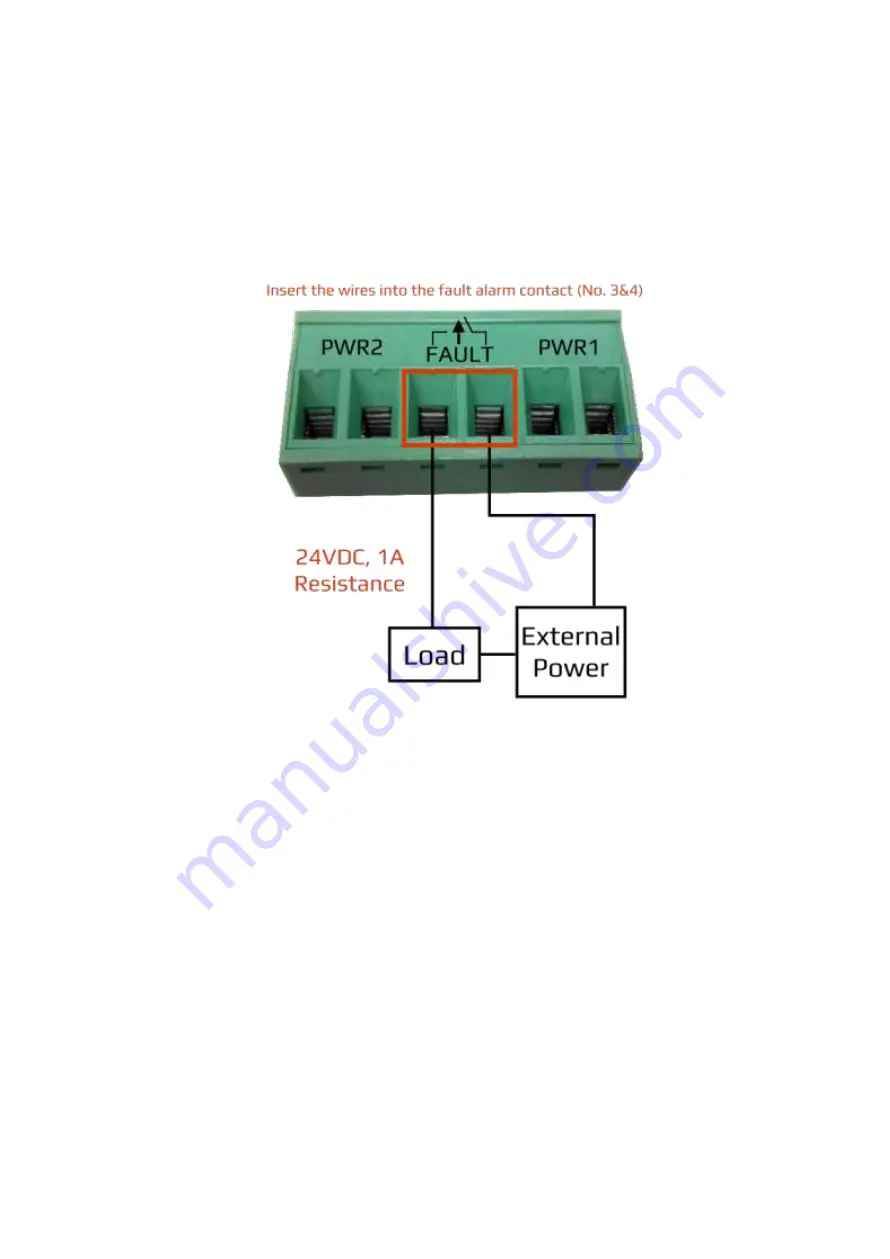
Wiring the Fault Alarm Contact
The fault alarm contact is in the middle of the terminal block connector as the picture shows below in
Figure 2.16. By inserting the wires, it will detect the fault status including power failure or port link
failure (managed industrial switch only) and form a normally open circuit. An application example for
the fault alarm contact is shown below in Figure 2.16.
Figure 2.16: Wiring the Fault Alarm Contact
Note:
The wire gauge for the terminal block should range between
12 ~ 24 AWG.
If only using one power source, jumper Pin 1 to Pin 5 and Pin 2 to Pin 6 to eliminate power
fault alarm.


