background image

Warning

This warning is presented for compliance with Califor-
nia Proposition 65 and other regulatory agencies and
only applies to the insulation in this product. This prod-
uct contains refractory ceramic, refractory ceramic fiber
or fiberglass insulation, which can produce respirable
dust or fibers during disassembly. Dust or fibers can
cause irritation and can aggravate preexisting respira-
tory diseases. Refractory ceramic and refractory
ceramic
fibers (after reaching 1000°C) contain crystalline silica,
which can cause lung damage (silicosis). The Interna-
tional Agency for Research on Cancer (IARC) has clas-
sified refractory ceramic fiber and fiberglass as possi-
bly carcinogenic (Group 2B), and crystalline silica as
carcinogenic to humans (Group 1).

The insulating materials can be located in the door, the
hearth collar, in the chamber of the product or under
the hot plate top. Tests performed by the manufacturer
indicate that there is no risk of exposure to dust or re-
spirable fibers resulting from operation of this product
under normal conditions. However, there may be a risk
of exposure to respirable dust or fibers when repairing
or maintaining the insulating materials, or when other-
wise disturbing them in a manner which causes
release of dust or fibers. By using proper handling pro-
cedures and protective equipment you can work safely
with these insulating materials and minimize any expo-
sure.
Refer to the appropriate Material Safety Data Sheets
(MSDS) for information regarding proper handling and
recommended protective equipment. For additional
MSDS copies, or additional information concerning the
handling of refractory ceramic products, please contact
the Customer Service Department at Barnstead
International at 1-800-553-0039.

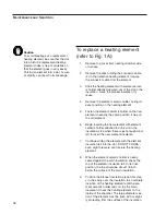
To avoid premature burnout of a replacement heating
element, be sure that the insulation tail supplied with
the replacement element is inserted between the two
legs of the element as shown in the drawing. Also be
sure that the heating element projects sufficiently into
the chamber. Insert element until welded portion
(where large diameter meets small diameter) projects
approximately 1/4" into inside of furnace chamber.

35

Maintenance and Servicing

Warning

To avoid electrical shock, this furnace
must always be disconnected from the
electrical supply prior to maintenance and
servicing. Do not clean clean furnace
without proper eye protection. Refer serv-
icing to qualified personnel.

Содержание F46110CM

Страница 1: ...M 8 Segment F46110CM 33 F46230CM 33 8 Segment F46118CM F46238CM 8 Segment F46120CM F46240CM 4 Program F46120CM 33 F46240CM 33 4 Program F46128CM F46248CM 4 Program F46120CM 75 F46240CM 75 20 Program F...

Страница 2: ...ler as a Single Setpoint Controller 21 Programming the Controller 21 Creating a New Program or Editing an Existing Program 21 Holdback 22 Setting Ramp Units 23 Setting Dwell Units 23 Setting the Numbe...

Страница 3: ...r nace specifications electrical source and grounding code requirements 2 Always be disconnected from the electrical supply prior to maintenance and servicing To avoid personal injury 1 Do not stand d...

Страница 4: ...carcinogenic Group 2B and crystalline silica as carcinogenic to humans Group 1 The insulating materials can be located in the door the hearth collar in the chamber of the product or under the hot plat...

Страница 5: ...g is not detrimental to the operation of the furnace A precious metal type B thermocouple senses the tempera ture in the chamber and transmits this information to the temperature control in millivolts...

Страница 6: ...any type end ramp by rate ramp by time to target dwell or step 2 The 4 program controller enables four 16 seg ment programs with 16 segments of any type end ramp by rate ramp by time to target dwell s...

Страница 7: ...file for Programmable Models Other Profiles May Be Formed Programmable Automatic Control Output 1 AUTO MAN Button PAGE Button SCROLL Button DOWN ARROW Button UP ARROW Button RUN HOLD Button Lower Disp...

Страница 8: ...4 40 12 Watts 9600 8320 9600 8320 9600 8320 2500 2500 2500 2500 2500 2500 Phase 1 1 1 1 1 1 Temp Range Cont 1700 C 1700 C 1700 C 1700 C 1700 C 1700 C Controller 8 Segment 8 Segment 4 Program 4 Progra...

Страница 9: ...24 Watts 9600 8320 9600 8320 9600 8320 5000 5000 5000 5000 5000 5000 Phase 1 1 1 1 1 1 Temp Range Cont 1700 C 1700 C 1700 C 1700 C 1700 C 1700 C Controller 8 Segment 8 Segment 4 Program 4 Program 20 P...

Страница 10: ...duct conforms with the technical requirements of the following standards EMC EN 50081 1 EN 50082 1 EN 61326 Safety EN 61010 1 EN 61010 2 010 per the provisions of the Electromagnetic Compatibility Dir...

Страница 11: ...pen the furnace door and remove packing material from inside the furnace chamber Vacuum the chamber prior to use to remove the insulation dust due to shipment A hearth plate is supplied with the furna...

Страница 12: ...connect ed as described Be sure to observe local wiring codes in connecting Initial Heatup Procedure The elements may bend slightly sideways due to electro magnetic forces generated between the elemen...

Страница 13: ...n 2 Do not operate or clean furnace without proper eye protection 3 Do not use in the presence of flammable or combustible materials fire or explosion may result This device contains components which...

Страница 14: ...r temperature protection and appropriate output switching devices to control the fur nace The digital readout continuously displays chamber upper display and setpoint lower display temperatures unless...

Страница 15: ...e the PAGE button until you reach the desired pa rameter To scroll through the desired parameter press and release the SCROLL button within the main list press and release the SCROLL button To quickly...

Страница 16: ...Starts a program when pressed once RUN light illuminates Holds a program when pressed again HOLD light illuminates Cancels hold and continues running when pressed again HOLD light is off and RUN ligh...

Страница 17: ...am models StAt Displays the program status OFF run running active program hoLd program on hold HbAc waiting for process to catch up End program completed in the lower display The controller will defau...

Страница 18: ...DOWN ARROW to select the hold back value in display units rmP U Press the UP or DOWN ARROW to toggle between ramp units SEc min or Hour Controller will default to SEc dwL U Press the UP or DOWN ARROW...

Страница 19: ...led this parameter sets the PV process value below which Pid1 proportional band integral time derivative time is active and above which Pid2 is active Pb Proportional band in display units SEt 1 ti In...

Страница 20: ...nsor break check that sensor is connected correctly L br Check that the heating circuits are working properly Ld F Load Failure indication of either an open or short solid sate relay a blown fuse miss...

Страница 21: ...rogramming A program is stored as a series of ramp and dwell segments and can be run once repeated a set number of times or run continuously To create a customized program using the controller paramet...

Страница 22: ...y from the setpoint before the holdback takes effect The program will resume when the error comes within the holdback value Holdback Type The holdback type is set when creating a new program Any of th...

Страница 23: ...oint in a specif ic amount of time See Setting the Segment Type for an explanation on hoe to set a ramp segment 1 Press the PAGE button until you reach the pro gram list ProG LiSt 2 Press the SCROLL b...

Страница 24: ...3 Press the UP or DOWN button to select the segment number Setting the Segment Type There are five segment types Proceed with the following steps according to the type of segment you have select ed r...

Страница 25: ...me 1 Press the PAGE button until you reach the pro gram list ProG LiSt 2 Press the SCROLL button until display reads tYPE 3 Press the UP or DOWN button until display reads rmP t 4 Press the SCROLL but...

Страница 26: ...P or DOWN button until the display reads StEP 4 Press the SCROLL button until display reads tGt 5 Press the UP or DOWN button to set a target setpoint cALL Running Multiple Programs To call a program...

Страница 27: ...Press the UP or DOWN button until display reads End 4 Press the SCROLL button until display reads End t 5 Press the UP or DOWN button to toggle between dwEll an indefinite dwell S OP End Segment Outp...

Страница 28: ...point temperature when external disturbances cause deviations from the setpoint Gain Scheduling Gain scheduling is the automatic transfer of control between to sets of PID values The 2408 controller d...

Страница 29: ...transfer point G SP the cal culated values will automatically be inserted into the PID1 set and if the process value is above G SP the calculated values will automatically be inserted into the PID2 se...

Страница 30: ...possible Adaptive tuning should be used when the characteristics of a process change due to load or setpoint changes or in a process that can not handle the oscillation caused by a one shot tune To t...

Страница 31: ...er a separate hearth plate should be used when possible In general space should be left on all sides of a load or on all sides of individual components of a load so that heat can penetrate through the...

Страница 32: ...ay be a risk of exposure to respirable dust or fibers when repairing or maintaining the insulating materials or when otherwise disturbing them in a manner which causes release of dust or fibers By usi...

Страница 33: ...possible that its calibration can drift particularly when operated near the upper temperature limit and especially in the presence of contaminants It is a good idea to inspect it at regular intervals...

Страница 34: ...ermocouple Replace thermocouple Slow heatup Operating 240V furnace Increase voltage to on 208V supply proper level Furnace chamber overloaded Lighten load Building or laboratory Fuses or breakers not...

Страница 35: ...fibers when repairing or maintaining the insulating materials or when other wise disturbing them in a manner which causes release of dust or fibers By using proper handling pro cedures and protective...

Страница 36: ...nt insulation tail into the slot DO NOT FORCE even slight pressure can fracture the heating element 8 When the element ceramic holder is nearly seated against the main insulation check the top of the...

Страница 37: ...Loosen connection block screws holding thermocouple noting which side of block the side of the thermocouple with the colored bead is connected to 5 Remove thermocouple 6 Install new thermocouple with...

Страница 38: ...ROLLER CURRENT CIRCUIT BREAKER FAN FAN CONTACTOR MECHANICAL TRANSFORMER THERMOCOUPLE INDICATOR LAMP HEATING ELEMENT DOOR SWITCH FL1 EMI LINE FILTER SWX163 EL461X1 PLX90 TCX5 TNX79 RYX62 FAX7 FAX7 SWX5...

Страница 39: ...ATURE CONTROLLER CURRENT CIRCUIT BREAKER FAN FAN FAN CONTACTOR MECHANICAL TRANSFORMER THERMOCOUPLE INDICATOR LAMP HEATING ELEMENT DOOR SWITCH CAX105 CN71X65 CN71X68 SWX54 FAX7 FAX7 FAX7 RYX62 TNX80 TC...

Страница 40: ...CEX135 16 req d Element connector cable 4 lg CE461X1 4 req d CE461X1 6 req d Element connector cable 10 Ig CE461X3 Element connector cable 14 lg CE462X1 Element connector cable 19 lg CE462X2 Element I...

Страница 41: ...his unit or can be obtained promptly from the factory When service or replacement parts are needed we ask that you check first with your dealer If the dealer cannot handle your request then contact ou...

Страница 42: ...42...

Страница 43: ...43...

Страница 44: ...ta tive ii misuse including use inconsistent with written operating instructions for the product mishandling con tamination overheating modification or alteration of the product by any customer or thi...

Отзывы: