background image

17

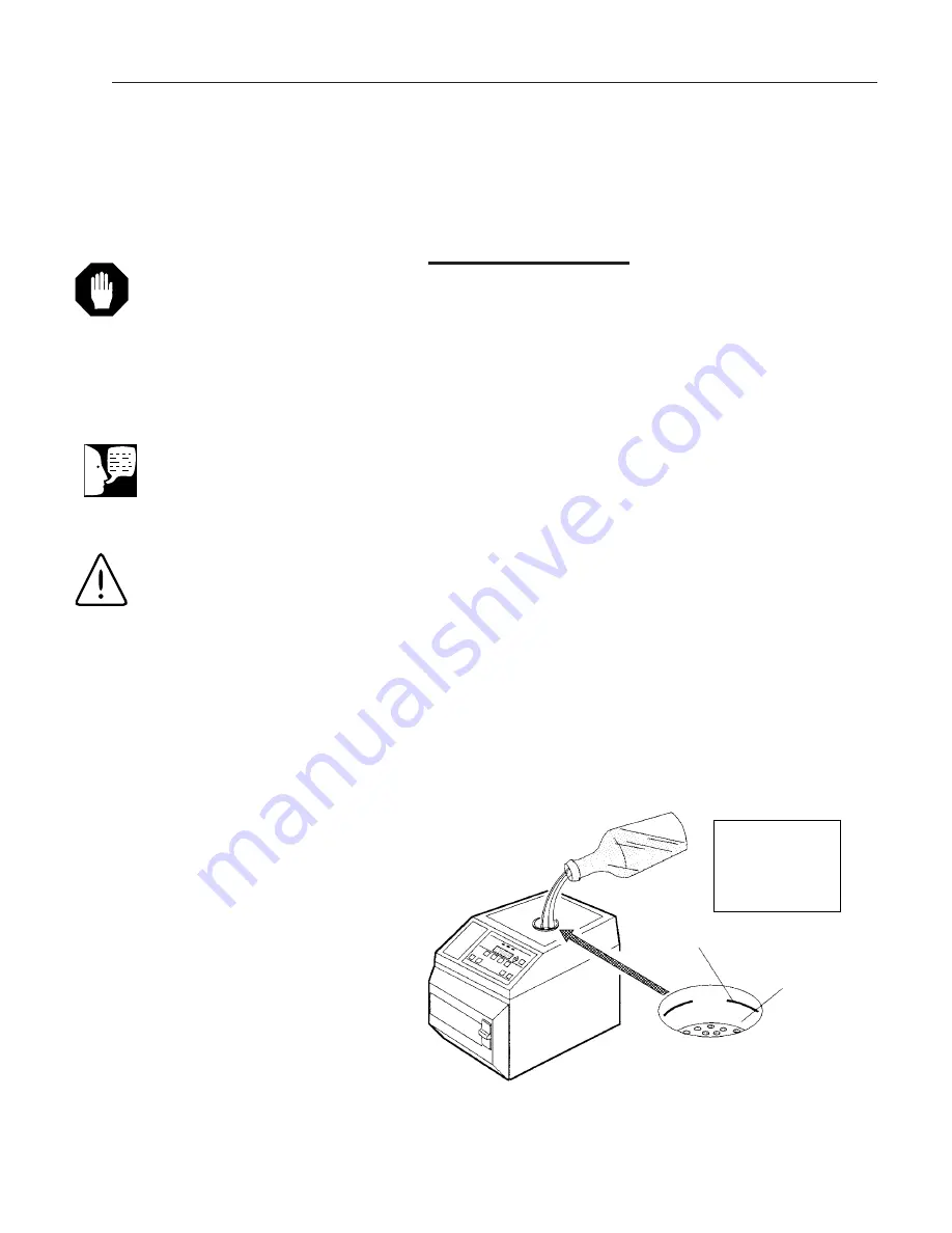
Filling Reservoir

Add distilled or low quality deionized water (minimum 0.5
megohm/cm, maximum 1.5 megohm/cm) to the reservoir
up to the fill line. The MC8 reservoir holds approximately 3
liters; the MC10 reservoir, 4 liters. Do not overfill.

O

PERATION

Figure 7
Filling Reservoir

Fill Funnel

Use Distilled

or Low Quality

Deionized Water

Only

Fill To Mark

Refill

Fill

Caution
Use only distilled or low quality
deionized water (minimum 0.5
megohm/cm, maximum 1.5
megohm/cm)
. Normal tap water
contains minerals that will corrode
sterilizer parts.

Warning
Burn Hazard: 
Do not add water to
the reservoir while sterilization cycle
is in progress. Steam vented into
reservoir at end of cycle could result
in possible burns.

The water in the reservoir could be
HOT if multiple cycles have been
run in succession.

Reservoir lid must be in place when
sterilizer is in use.

Note
Be sure reservoir drain valve is
closed before filling the reservoir.

Содержание Harvey Hydroclave MC10

Страница 1: ...1 Harvey Hydroclave MC8 Hydroclave MC10 Steam Sterilizer With Optional Non Recirculating System OWNER AND OPERATOR MANUAL LT1203X1 5 11 04 ...

Страница 2: ...am 13 Operation 15 Power On Controls On 16 Filling Reservoir 17 Filling Non Recirculating Tank Option 18 Emptying Collection Bottle 18 Installing Overflow Tube Optional 19 Load Chart 20 Preparing Items for Sterilization 21 Loading 21 Selecting Cycle 22 Starting Cycle 23 Drying Phase 23 Open Door Drying 24 Removing Load 24 Additional Information 25 Cancel Cycle 25 Emergency Power Off 25 Power Failu...

Страница 3: ...leaning Printer Recess MC10 34 Replacing Door Gasket 35 Every 6 Months 36 Cleaning Non Recirculating Water Cooling Tank 37 Recommended Spare Parts 38 Installation 39 Leveling Sterilizer Cabinet Clearance Electrical Connection 39 Non Recirculating Water Accessory Installation 40 Setting the Clock Calendar 41 Technical Data 46 Appendix 47 Voltage Conversion Dual Voltage Models Only 47 115 VAC to 230...

Страница 4: ...he information included in this manual applies to all models unless noted for specific models We urge you to read this manual carefully before operating the unit and retain it for future reference Operation Overview Hydroclave MC8 and MC10 Steam Sterilizer The MC8 and MC10 sterilizer operates on the principle of heated water converted to steam in a sealed pressure chamber What happens when the con...

Страница 5: ... At the completion of the exposure time a sole noid valve opens allowing the steam and water to vent back into the reservoir The steam reenters the reservoir through tubing below the water level in the reservoir The water in the reservoir condenses the steam to a liquid for reuse in the next cycle When the vent is complete an indicator light on the control panel lights to alert the operator that t...

Страница 6: ...MC8 and MC10 steam sterilizer Even when distilled or deionized water is used some contaminants can collect in the chamber rack and trays Clean the reservoir reservoir filter and chamber screen at least every 25 cycles A clogged filter and or screen will result in restricted water flow and prolong the time it takes to fill the chamber Maintaining a clean reservoir filter and chamber screen is espec...

Страница 7: ...Electrothermal Engineering Ltd 419 Sutton Road Southend On Sea Essex SS2 5PH United Kingdom Copies of the Declaration of Conformity are available upon request This equipment has been tested and found to comply with the limits for a Class A digital device pursuant to Part 15 of the FCC rules These limits are designed to provide reasonable pro tection against harmful interference when the equipment ...

Страница 8: ...eptacle Attention Consult Accompanying Documents Refer to Warning and Caution notes in this manual Type B Equipment Class I Refer to IEC Standard 601 1 OFF Only for a part of equipment ON Only for a part of equipment Paper Feed Does not disconnect equipment from mains voltage AC power ...

Страница 9: ...er Accessory Optional Drain Tube Open Lock Printer Receptacle MC8 Fuse s Power Cord Discharge Port Non Recirculating Pressure Relief Valve Water Fill Port Chamber Filter Screen Reservoir Drain Valve Door Gasket Leveling Feet Push To Release Release Tab Click In To Drain Drain Fitting Reservoir Filter Screen Locking Handle ...

Страница 10: ...r liquid cycle Drying times are adjustable Cycle runs automatically when START switch is pressed Optional printer records temperature and pressure during cycle Chamber temperature may be displayed in C or F Chamber temperature is displayed continuously throughout cycle excluding dry phase and may be displayed in psi kPa or bars Messages may be displayed in English French Spanish or German Clock fo...

Страница 11: ...11 GENERAL DESCRIPTION Figure 1 Control Panel Harvey Hydroclave MC8 Cycle Phase Indicators Cycle Select Switches ...

Страница 12: ...essories MC8 MC10 Support Flange Tray Rack MC8 Part No 265002 MC10 Part No 2 513025 Large Tray Part No 2 67811 Small Tray Part No 265001 Wrapped Cassette IMS Cassette Not Sold By B T IMS Cassette Rack Holds MC10 Part No 260761 Four Tray Rack MC8 Part No 265024 Trays MC8 MC10 ...

Страница 13: ...ing tank This feature allows the excess water to drain directly into a sink or drain if available eliminating the need to periodically empty the collection bottle Recommended Steam Sterilization Monitoring Program All functions of the sterilizer should be monitored to provide maximum sterilization assurance The Joint Commission on Accreditation of Hospitals and the American Dental Association reco...

Страница 14: ... vials Spore Population 106 AY759X8 Process Indicators Chemical Indicator Strips Box of 250 Steam Sterilizers Only AY759X2 Chemitest Indicator Tape Closure system for packs bags or other containers 260577 Roll is 1 5 3 8 cm x 360 L 91 4 mm Chemitest Indicator Strips Box of 250 Chemiclave Sterilizers Only 230305001 Chemitest Indicator Tabs Roll of 250 Self adhering tabs 1 5 3 8 cm sq 230306001 Inst...

Страница 15: ... 7 Open Door to Dry 8 Remove Load Optional Drying phase if selected will start automati cally without opening the door Opening the door however may improve drying efficiency Operation Operation Warning Patient Safety Zone Do not oper ate this sterilizer within 6 ft 2 m of patient treatment point ...

Страница 16: ... temperature exposure time and drying time will be displayed and the Standby Mode will begin During the Standby Mode the heater turns on to warm the cham ber to approximately 38 C The heater then cycles ON and OFF to maintain the warm temperature 3 Turn ON the optional printer see Printer sec tion OPERATION Power On Controls On Note If time and date are incorrect reset the clock calendar ...

Страница 17: ...l Caution Use only distilled or low quality deionized water minimum 0 5 megohm cm maximum 1 5 megohm cm Normal tap water contains minerals that will corrode sterilizer parts Warning Burn Hazard Do not add water to the reservoir while sterilization cycle is in progress Steam vented into reservoir at end of cycle could result in possible burns The water in the reservoir could be HOT if multiple cycl...

Страница 18: ...ter Cooling Tank Collection Bottle From Sterilizer Figure 8 Non Recirculating Water Accessory Fill With Distilled or Low Quality Deionized Water Until It Overflows Into the Collection Bottle Approx 3 Gal Collection Bottle Remove Cap Optional Overflow Drain Full Mark Note The cooling tank must be connected to the sterilizer before filling the tank with water Note Do not operate sterilizer unless th...

Страница 19: ...olatile substances or for any purpose other than its intended design Failure to observe this warning could cause personal injury or damage to equip ment Warning Burn Hazard To prevent the possi bility of injury from liquids boiling over and or containers exploding use only self venting automatic seal ing stoppers recommended by man ufacturers when processing all con tainer liquids or media Caution...

Страница 20: ... s e t t e s s a c S M I e e r h T s b l 5 1 d e p p a r w e l g n i s h c a e g 0 8 6 y t n e w t r o s e h c u o p 0 1 x 6 t h g i E d e g n i h o w t s e h c u o p 5 x 3 h c u o p r e p s t n e m u r t s n i r o s e h c u o p 0 1 x 6 n e e t r u o F s e h c u o p 5 x 3 t h g i e y t n e w t r e p s t n e m u r t s n i d e g n i h o w t h c u o p s k c a P k c a p 9 5 c e p s A D A e n O s k c a...

Страница 21: ...sterilizer piping This could eventually cause partial restriction of water flow and the need for possible service Unwrapped goods can be placed directly on tray liner in the bottom of the tray Do not use paper towels Open all hinged instruments Uncover empty containers and place them on their sides Device manufacturers i e manufacturers of handpieces and specialty items instructions must be follow...

Страница 22: ...cle Figure 11 Selecting Cycle s t n e m u r t s n I d e p p a r w n U m u m i n i m s e t u n i m 3 s t n e m u r t s n I d e p p a r W m u m i n i m s e t u n i m 5 s k c a P m u m i n i m s e t u n i m 0 3 s d i u q i L m u m i n i m s e t u n i m 0 3 Figure 10 Locking the Door Push Down Firmly Note Whether using the two tray four tray or IMS cassette rack items being processed should be evenly ...

Страница 23: ...icient drying opening the door is strongly rec ommended See Open Door Drying procedure At the end of closed door drying three groups of three beeps will sound and the COMPLETE indicator lights To cancel drying phase in progress press the STOP switch Figure 12 Starting Cycle OPERATION Note The open door drying time is limited to the selected closed door drying time If zero is selected open door dry...

Страница 24: ...ne minute OPERATION Figure 13 Drying Cycle Operation Latch Handle Down With Door Open Door Slightly Open Approx 1 4 Latching Bars Note Closed door drying will stop when the door is opened When START is pressed to begin open door drying the timer will be reset to the pro grammed drying time The open door drying time is limited to the selected closed door drying time If zero was selected open door d...

Страница 25: ...the power interruption If you cannot start a cycle after power is restored 1 Unplug the unit 2 Press and hold the OFF button while plugging the unit back in 3 Release the OFF button after PERFORMING SELF TEST is displayed Warning Volatile Reaction Do not open the door if there is a liquid load in the chamber The containers may boil over or explode Call for authorized service Caution The door will ...

Страница 26: ... C R E B M A H C k c e h C r o o d n e p o n e h t l o o c o t r e b m a h c r o f t i a W r e t l i f r e b m a h c n a e l c r o r e b m a h c n i s i r b e d r o f f i e c i v r e s l l a C n i a g a e l c y c n u r d n a d a o l s s e c o r p e R w o r a n i s e l c y c o w t s r u c c o e g a s s e m N E P O R O O D D E L E C N A C E L C Y C D A O L S S E C O R P E R n w o d s s e r P d e h c...

Страница 27: ... e z i l i r e t S f o n o i t e l p m o c r e t f a h g u o n e e l c y c e z i l i r e t s t e w y l e v i s s e c x e d a o L e g r a l o o t e z i s d a o L s l l a w r e b m a h c g n i h c u o t d a o L y a r t f o m o t t o b n i d a o l d e p p a r W y l n o r e b m a h c 0 1 k c a r r a f t o n r o r a f o o t n e p o r o o D h g u o n e e m i t g n i y r d e s a e r c n I a f o n o i t e...

Страница 28: ... installed If a printer is added later it should be installed by an authorized service technician Operation The printer provides hard copy documentation of each cycle An ON OFF PAPER FEED switch is provided on the printer A pilot light indicates when the printer is acti vated Printer Figure 16 Sample Printout Figure 15 On OFF Paper Feed Switch Push Hold ...

Страница 29: ...emove the ribbon cover press down as shown Lift the cover up and out 2 To remove the ribbon press down as shown Grasp the ribbon and lift it from the printer 3 Press the new ribbon down until it snaps into place 4 Install paper roll 5 Snap cover back in place PRINTER Press Figure 17 Paper Roll Replacement Be Sure Feed End is Cut Straight Across Spindle Slot Shiny Metal Strip Paper Roll Paper Roll ...

Страница 30: ...ess 2 Rest the printer on the top cover while cleaning the recess It is not necessary to disconnect the printer cables 3 When installing the printer tuck the excess cable into the recess PRINTER Figure 20 Printer Removal Lift the Printer Out Wipe With Wet Cloth ...

Страница 31: ...ber at room temperature Wipe all residue from the surfaces with a dampened lint free cloth Operator Maintenance Figure 22 Cleaning Chamber Rub Area To Be Cleaned Rinse with Water and Wipe Clean Figure 21 Door Gasket Wipe With Clean Damp Cloth Hot Surface Burn Hazard Be sure sterilizer is cool before cleaning door gasket and mating surface Hot Surface Burn Hazard Be sure sterilizer is cool before c...

Страница 32: ...in hose and fitting 4 Store the drain tube and fitting OPERATOR MAINTENANCE Figure 23 Draining Reservoir Warning Water May Be Hot Drain Fitting Click In To Drain Release Tab Push To Release Drain Port Figure 24 Cleaning Reservoir Clean Reservoir With Disinfectant Rinse Thoroughly Before Filling With Distilled Water Caution Do not use steam to disinfect or clean the sterilizer cabinet Extreme high ...

Страница 33: ...thod does not effectively clean the filter replace it Cleaning Chamber Filter Screen 1 Pull the filter screen assembly out of the water fill port inside the chamber 2 Clean any deposits from the screen using a small stiff bristled brush toothbrush or ultra sonic cleaner 3 When clean push the open end of the filter screen into the water fill port in the back of the chamber OPERATOR MAINTENANCE Figu...

Страница 34: ...re Use a mild disinfectant to clean the recess OPERATOR MAINTENANCE Figure 27 Emptying Non Recirculating Collection Bottle Collection Bottle Empty Contents Down The Drain Note The fill port is the bottom hole in the back of the chamber The top hole is for the temperature probe and should not be obstructed Hot Surface Burn Hazard Do not empty the col lection bottle when the sterilizer is in operati...

Страница 35: ...n ter stud of the door plate 4 Insert the retainer inside the gasket outer lip of retainer against gasket as shown 5 Slide the gasket and retainer assembly onto the center stud of the door plate and secure it finger tight firm Do not use wrench Figure 28 Door Gasket Replacement Silicon RTV Sealant Gasket Gasket Retainer Hex Nut Hole at 4 00 position Gasket Retainer Chamber Side Gasket Door Side Se...

Страница 36: ...e malfunctions the valve must be replaced Call for authorized service 4 Cancel cycle after checking valve to prevent overheating OPERATOR MAINTENANCE Figure 29 Pressure Relief Valve Note If traces of steam continue to escape through the valve the valve has not re seated properly Open and close the valve quickly several times if neces sary by pulling the ring and letting it snap closed Warning Burn...

Страница 37: ...f household bleach 3 4 cup and distilled or deionized water 1 gal Drain solution and rinse with distilled or deionized water before refilling Clean filter in the inlet line fitting before connecting to sterilizer Refill the tank with clean distilled or low quality deionized water minimum 0 5 megohm cm maximum 1 5 megohm cm to put the system back in service Hot Surface Burn Hazard Do not clean the ...

Страница 38: ... u F D T e p y T 2 6 0 3 4 6 2 m m 0 2 x 5 t l o v 0 5 2 p m A 8 l e d o M t l o v 0 3 2 e s u F D e p y T 2 6 7 0 5 6 2 r e t l i F r i o v r e s e R n e e r c S 1 1 8 0 5 6 2 n i a r D r e b m a h C n e e r c S 1 4 0 9 9 6 2 8 C M t e k s a G r o o D 1 5 0 0 3 1 5 2 0 1 C M t e k s a G r o o D 1 4 8 2 0 6 2 s l l o r 6 f o x o b l l o R r e p a P 1 6 1 1 4 6 2 n o b b i R r e t n i r P 1 1 0 1 0...

Страница 39: ...arate Circuit Installation Warning Explosion Hazard Do not locate this steril izer in areas where explosive anesthetics are used or stored An explosion could occur causing possible equipment damage and injury for personnel Note The MC8 weighs 55 lbs 25 kg the MC10 weighs 70 lbs 32 kg The sterilizer should be lifted by two persons and trans ported on a cart Note Do not operate this sterilizer withi...

Страница 40: ...ting discharge port Step 3 Automatic Optional Overflow Push the overflow tube into the overflow connector at the top of the cooling tank until it clicks Tighten nut finger tight plus 1 4 turn with wrench 1 4 Turn Tank Drain Connector Discharge Hose Non Recirculating Discharge Port Cap Be sure connection nut is started straight Cross threading will cause leaks and damage the nut and fitting Do Not ...

Страница 41: ...w to set the hour ahead or the down arrow to set it back When the clock is set to the correct hour press PROGRAM SET to store the hour in memory b The minute will flash Use the arrows to set the minute Press PRO GRAM SET to store c The AM PM indicator will flash Press either arrow to alternate between AM and PM Press PROGRAM SET to store d The month will flash 12 00 AM JAN 01 1998 12 00 AM JAN 01 ...

Страница 42: ... to store e The day will flash Use the arrows to set the day Press PRO GRAM SET to store f The year will flash Use the arrows to set the year Press PRO GRAM SET to store 3 The clock calendar is now ready 12 00 AM JAN 01 1998 12 00 AM JAN 01 1998 INSTALLATION ...

Страница 43: ...lease the PROGRAM SET switch The sterilizer is now ready for you to proceed with Step 2 INSTALLATION Note This operation requires the use of two hands You must tell the steriliz er that the non recirculating feature is ready This only takes a few sec onds If at any time you wish to dis continue this activation mode press cycle stop Warning Non Recirculating Option must be installed before proceedi...

Страница 44: ...RAM SET Press PROGRAM SET Press PROGRAM SET Press PROGRAM SET INSTALLATION LOG ERXX XXXXX DATE TIME PRESSURE UNITS PSI TEMPERATURE CELSIUS 12 HOUR CLOCK DIAGNOSTICS NO LANGUAGE ENGLISH CONFIGURATION HARVEY Caution The following messages will appear Failure to follow these instructions may result in improper operating conditions ...

Страница 45: ... SET 3 When RECIRCULATE is displayed press either the up or down arrow to change to NON RECIRCULATE Press PROGRAM SET Press STOP This will revert back to the main display menu time and date STANDARD UNIT INSTALLATION MODEL MC8 OR MC10 RECIRCULATE STERILIZE ...

Страница 46: ... quarts Maximum Rated 45 psi 310kPa 45 psi 310 kPa Operating Pressure Environmental Conditions Operation 10 to 40 C 50 to 104 F 10 to 40 C 50 to 104 F 30 to 70 relative humidity 30 to 70 relative humidity non condensing non condensing Altitude Limit 2 000 meters 2 000 meters Storage and Transport 20 to 60 C 4 to 140 F 20 to 60 C 4 to 140 F 10 to 100 relative humidity 10 to 100 relative humidity Pr...

Страница 47: ... or save for future reconversion Appendix Figure 31 Removing access panels Power I O Board Terminal Block Transformer PC Board MC10 Printer Option Warning Unplug power cord before removing any access panels Voltage conver sion should be performed by a quali fied service technician Note Dual voltage models have both volt ages listed on the rating plate Do not attempt to convert a unit that does not...

Страница 48: ...ter wire from J14 to J11 Leave other black wire connected 3 On the Printer Power PC Board MC10 with Printer Only Remove jumpers from JMP1 and JMP2 positions and install jumper in JMP3 posi tion Save other jumper for future reconversion to 115 VAC 4 Install the 8 Amp fuses in fuseholders 5 Reinstall the left side panel rear access panel and pressure relief valve deflection cover 6 Use either a plug...

Страница 49: ...49 49 APPENDIX Figure 32 Power I O PC Board 230 VAC ...

Страница 50: ...50 50 Figure 33 MC10 Printer Power Supply Board 230 VAC APPENDIX ...

Страница 51: ...from J11 to J14 Move white heater wire from J12 to J11 Leave the other black wire connected 3 On the Printer Power PC Board MC10 with printer only Remove jumper from JMP3 posi tion and install jumpers in JMP1 and JMP2 positions 4 Install the 15 AMP fuses in fuseholders 5 Reinstall the left side panel rear access panel and pressure relief valve deflection cover 6 Use either a plug adapter or remove...

Страница 52: ...52 52 Figure 34 Power I O Board 115 VAC APPENDIX ...

Страница 53: ...53 53 APPENDIX Figure 35 MC10 Printer Power Supply Board 115 VAC ...

Страница 54: ...54 ...

Страница 55: ...55 ...

Страница 56: ...tative ii misuse including use inconsistent with written operating instructions for the product mishandling contamination overheating modification or alteration of the product by any customer or third party or iii use of replacement parts that are obtained from a party who is not an authorized dealer of BARNSTEAD Heating elements because of their susceptibility to overheating and contamination mus...

Отзывы: