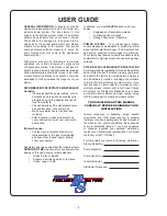
Barnes EcoTRAN Скачать руководство пользователя страница 4

4

GENERAL INFORMATION

 - In general, your home 

wastewater disposal service is part of a larger low-
pressure  sewer  system.  The  key  element  in  this 
system  is  the  Barnes  grinder  station.  The  station 
collects  all  wastewater  from  your  house  or  facility. 
The  solids  in  the  sewage  are  then  ground  into  a 
small  size  by  the  grinder  pump  within  your  station, 
suitable  for  pumping  in  the  system.  The  grinder 
pump  generates  suffi cient  pressure  to  pump  the 
slurry  created  from  your  home  to  the  wastewater 
treatment plant. 

With  proper  care  and  by  following  a  few  simple 
guidelines,  your  station  will  give  you  many  years 
of  dependable  service.  The  station  is  designed  to 
handle routine, domestic and light industrial sewage. 
Solid waste materials should be thrown in the trash. 
A  preventative  maintenance  schedule  should  be 
developed  to  further  increase  the  longevity  of  your 
station.

RECOMMENDED PREVENTATIVE MAINTENANCE


Annually:


•  Visually inspect the power cables, control


harnesses and rope. Make sure they are


properly hung on the adapter hooks and


free from defects.


•  Check operation of the visual alarm lamp


and audible siren in the alarm box


•  Make sure alarm box is free from any 


moisture.


•  After inspection, make sure alarm box 


cover and system rock cover are secure 


and locked.

If Alarm Sounds:


•  Contact your local authorized service


representative or the local municipality 


and have them inspect and/or trouble 


shoot your system.

Regulatory agencies advise that the following items 

SHOULD NOT BE

 introduced into any sewer either 

directly or through a drain or waste disposal:

• 

Glass, metal, or plastic

• 

Diapers, Sanitary napkins, or tampons

• 

Socks, rags, or cloth

In addition, you must 

NEVER

 introduce into any 

sewer:

• 

Explosives or Flammable material

• 

Lubricating oils or Grease

• 

Strong Chemicals or Gasoline

POWER  FAILURE

  –  Your  grinder  pump  station 

cannot dispose of wastewater or provide an alarm 
signal without electrical power. If an electrical out-
age occurs, keep your water usage to a minimum. 
Your station has reserve capacity available to help 
avoid alarm or high-level occurrences during power 
outages.

STATION START-UP/WARRANTY REGISTRATION


A start-up/warranty registration form is included in the 
back of this manual. It must be properly completed 
and sent to the factory for review before a warranty 
can be activated. Invalid or missing data or failure 
to return the form will delay or void warranty. If you 
feel you have a claim under the provisions of your 
warranty,  please  contact  your  local  Crane  Pumps 
& Systems, Inc. Distributor. Please be sure to have 
your station part number and model number along 
with the pump part number and model number.

YOU SHOULD READ THIS MANUAL 

CAREFULLY BEFORE BEGINNING YOUR 

INSTALLATION!

Various  references  to  ballasting,  proper  backfi ll 
procedures,  and  other  steps  required  to  properly 
install your new basin package are located throughout 
the  manual.  You  should  understand  these  aspects 
to  avoid  installation  issues.  If  you  have  questions 
or  concerns  regarding  your  particular  installation, 
contact  your  local  Barnes  representative  or  contact 
the factory at (937) 778-8947.

For future reference, record the following information:
Station Serial No:

Pump Model No:

Pump Serial No:

Local Distributor:

Distributor Telephone:

USER GUIDE

Содержание EcoTRAN

Страница 1: ...onstant product improvement program product changes may occur As such Crane Pumps Systems reserves the right to change product without prior written noti cation 420 Third Street 83 West Drive Bramton...

Страница 2: ...NLET LOCATION Installing Flexible Inlet Flange 17 Step 10C BACKFILLING 18 Step 11 INSTALLING DIRECT BURIAL CABLE Mounting alarm box 19 Step 12 BACKFILLING and FINAL GRADING 20 SYSTEM ELECTRICAL WIRING...

Страница 3: ...operation unless advised otherwise by the proper authorities Before removing the pump from the basin be sure to close the shut off valve This prevents back ow from the pressure sewer Keep the control...

Страница 4: ...ctly or through a drain or waste disposal Glass metal or plastic Diapers Sanitary napkins or tampons Socks rags or cloth In addition you must NEVER introduce into any sewer Explosives or Flammable mat...

Страница 5: ...d remove cover STEP 2 Cut the banding that retains the tank and discard Cut the banding that hold the two boxes together STEP 3 Roll the tank to its right side up position and remove the level control...

Страница 6: ...NG FLEXIBLE DISCHARGE FITTING 2 PAD LOCKS PIPE LUBE PUMP LIFTING HARNESS 1 4 20 x 1 5 FASTENERS BASIN TANK ASSEMBLY TANK RECEIVER POD w HARNESS BALL VALVE REBAR EcoTRAN GRINDER PUMP ESPS LEVEL CONTROL...

Страница 7: ...means of shutting main sewage line off from individual station Material Bronze body with 300 series stainless steel ball and stem with te on seats FEMALE RECEIVER Seal tank and adapt from ball valve...

Страница 8: ...ou have the necessary equipment and supplies before starting your installation see lists below EQUIPMENT REQUIRED LIST NOT INCLUDED 3 8 WRENCH LARGE NYLON LIFTING STRAP S REGULAR AND PHILLIPS SCREWDRI...

Страница 9: ...One Call information http www call811 com The location of your basin should meet the following conditions Not placed in low lying or frequently ooded areas Ground slopes away from the basin Have well...

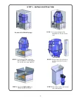
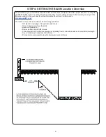
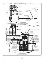
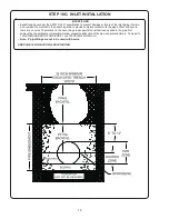
Страница 10: ...10 STEP 4 SETTING THE BASIN Location Overview...

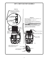
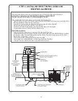
Страница 11: ...11 STEP 5 RISER TANK PARTS ASSEMBLY...

Страница 12: ...ructural damage Handle the tank in a vertical manner whenever possible Never place a chain around the basin when moving the tank Only use a nylon lifting strap or similar device around the tank Never...

Страница 13: ...RED TO BRING DRAIN TILE ABOVE GRADE LEVEL USE CRANE PUMPS SYSTEMS DRAIN TILE EXTENSION KIT P N 123510 Step 1 On riser trim top side edge at cut zone The cut zone is just above the corregation as shown...

Страница 14: ...p See Fig 6 Step 6 Insert and tighten cord grip in tapped hole until the hex ange of the cord drip meets the riser wall See Fig 7 Step 7 Loosen cord grip nut then feed direct burial cable through the...

Страница 15: ...t must have a minimum of 1 3 cubic yard of concrete and the speci ed minimum s shown below STEP 8 BALLASTING REQUIREMENTS IMPORTANT FAILURE TO BALLAST STATION WILL VOID WARRANTY AND MAY RESULT IN PERS...

Страница 16: ...rce main connection for station isolation from main This valve is to be placed between the force main and redundant check valve Pipe of proper size and strength for rated conditions supplied by others...

Страница 17: ...otentially overwork the treatment facilities WHAT TO DO Verify pipe O D The inlet tting is sized for 4 inch Schedule 40 80 and SDR 35 MUST have a minimum of 1 8 per foot drop If required only use 45 d...

Страница 18: ...pipe bottom and ensure there are no voids The material in the haunching area supports the vertical load applied to the pipe Not compacting the embedment material will allow excessive de ection of the...

Страница 19: ...nicked insulation or conductors All cable is ran inside of conduit when going from the Alarm Box to 24 below grade All connections made are utilizing Third party listed devices MOUNTING ALARM BOX Make...

Страница 20: ...rials offer high stiffness and strength and depending on the amount of nes may be relatively free draining Examples of material types Angular crushed stone or other Class 1A materials and stone sand m...

Страница 21: ...L 110 127V 60Hz 1 2 3 4 ETM1 SR PUMP TO RUN PUSH O1 ORANGE R1 RED SERVICE DROP CABLE CABLE FROM BASIN ORDER PER TERM STRIP STEP 13 WIRING THE STATION TO ALARM BOX Strip the outer jacket of the cord o...

Страница 22: ...Options for running cable from the service supply to the alarm panel A 1 10AWG cable with four conductors plus a ground 5 separate leads OR B 1 10AWG two conductor with ground and 1 14AWG two conduct...

Страница 23: ...the cord plug into the housing bore aligning the alignment mark of the plug with the alignment hole of the terminal block see below Tighten bolts on compression ange until it touches the housing Pump...

Страница 24: ...er Using the cover as a template pilot drill the screw holes into the riser using an drill bit as shown in Fig 11 Step 11 Attach the cover using the provided screws and washers Hand tighten screws as...

Страница 25: ...valve upper moveable and support ange This will guide the pump down the guide rail and rest on the stop built into the POD Pump Orienting Device Check to make sure the check valve is aligned as shown...

Страница 26: ...D ROCK COVER INSTALLATION The cover gasket is a large soft O ring that is factory installed Lube the O ring lightly with the provided lube Then install the cover The rock cover is secured with a twist...

Страница 27: ...s been installed in the service disconnect panel Proper gauge and conductor wire installed from service disconnect to house panel All terminal connections are secure Circuit breakers in the Alarm Box...

Страница 28: ...or is into cold areas 7 Remove and examine check valve for freedom of operation 8 Open valve 9 Check impeller for freedom of operation security and condition Clean impeller cavity and inlet of any obs...

Страница 29: ...colder months proper steps should be taken to ensure uninterrupted use upon restarting the basin Remove the basin rock cover and check the liquid level Fill the station with water until the pump turns...

Страница 30: ...30 11 23 13 12 29 4 15 16 18 17 6 5 7 26 25 32 9 8 2 1 31 17...

Страница 31: ...Flexible Inlet Fitting 12 4 119081 FHHS Screw 1 4 20 x 1 00 Lg 13 1 100159 Flexible Discharge Fitting 15 1 118259 Valve Receiver Grommet 16 1 118245 Ball Valve 17 2 625 01558 O Ring 18 1 118247 POD 2...

Страница 32: ...between the results of eld testing conducted by or for user and laboratory tests corrected for eld performance the latter shall control RECOMMENDATIONS FOR SPECIAL APPLICATIONS OR THOSE RESULTING FROM...

Страница 33: ...t To Insure That Employees Will Not Be Exposed To Health Hazards In Handling Said Material All Applicable Laws And Regulations Shall Apply IMPORTANT WARRANTY REGISTRATION Your product is covered by th...

Страница 34: ...___ Type _________________________________ Number and size of short circuit device s ___________ Amp rating ___________________ Overload Type _____________ Size ______________ Amp rating _____________...

Страница 35: ...ls installed away from turbulence YES___ NO___ Is level control operating properly YES___ NO___ Is pump fully submerged during operation YES___ NO___ Follow up Corrective Action Required YES___ NO___...

Страница 36: ...Notes...

Отзывы: