Barnes 2SEV-DS Series Скачать руководство пользователя страница 12

12

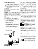
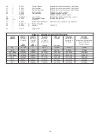
TABLE 1 - COOLING OIL - Dielectric

SUPPLIER

GRADE

BP

Enerpar SE100

Conoco

Pale Paraffin 22

Mobile

D.T.E. Oil Light

G & G Oil

Circulating 22

Imperial Oil

Voltesso-35

Shell Canada

Transformer-10

Texaco

Diala-Oil-AX

Woco

Premium 100

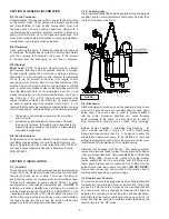
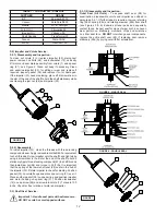
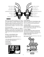
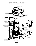
F-2) Impeller and Volute Service:

F-2.1) Disassembly and Inspection:

To clean out volute (1) or replace impeller (33), disconnect 

power, remove hex bolts (26), and lockwasher (12), vertically 

lift motor and seal plate assembly from volute (1) and spacer 

ring (31), see Figure 4. Clean out body if necessary. Clean 

and examine impeller (33), for pitting or wear and replace if 

required, inspect gasket (36) and replace if cut or damaged. 

If the impeller (33) needs replacing, place a flat screwdriver in 

the slot of the end of the shaft to hold the shaft stationary while 

unscrewing the jam nut (66) and impeller (33).
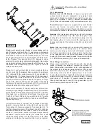
F-2.2) Reassembly:

To install impeller (33), clean the threads with thread locking 

compound cleaner. Apply removable Loctite® 603 or equivalent 

to shaft threads. Screw impeller onto the shaft hand tight while 

using a screwdriver in the slot at the end of the shaft to hold it 

stationary. Apply thread locking compound (57) to shaft threads 

then install jam nut (66) and torque to 40 ft. lbs. It is important 

that the spring of the lower shaft seal (28) seats in the hub of 

the impeller (33). Rotate impeller to check for binding. Position 

gasket (36) on volute flange and place spacer ring (31) over it. 

Place another gasket (36) on spacer ring and position impeller 

and motor housing on spacer ring (31). Position lockwasher 

(12) on cap screw (26) and screw into volute (1). Torque to 100 

in-lbs. Check for free rotation of motor and impeller.

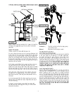
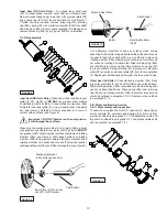
F-3) Shaft Seal  Service:

Important ! - Handle seal parts with extreme care. 

DO NOT scratch or mar lapped surfaces.

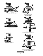
F-3.1) Disassembly and Inspection:

Outer Seal (All Units) -

 To expose shaft seal (28) for 

examination, disassemble volute and impeller as outlined in 

paragraph F-2.1. If further repair is required, remove retaining 

ring (28d), spring (28c) and rotating member (28b) from shaft 

(see Figures 5 & 6). Examine all seal parts and especially 

contact faces. Inspect seal for signs of wear such as uneven 

wear pattern on stationary members, chips and scratches 

on either seal face. 

DO NOT 

interchange seal components, 

replace the entire shaft seal (28). If replacing seal, remove 

stationary (28a) by prying out with flat screwdriver.

FIGURE 6 - DOUBLE SEAL

FIGURE 6 - SINGLE SEAL

FIGURE 7

FIGURE 5

Содержание 2SEV-DS Series

Страница 1: ...ct improvement program product changes may occur As such Crane Pumps Systems reserves the right to change product without prior written notification 420 Third Street 83 West Drive Bramton Piqua Ohio 4...

Страница 2: ...ig 17 19 DOUBLE SEAL CROSS SECTION Fig 18 20 DOUBLE SEAL EXPLODED VIEW Fig 19 21 PARTS LIST 22 24 RETURNED GOODS POLICY 28 WARRANTY 27 WARRANTY REGISTRATION SPECIAL TOOLS AND EQUIPMENT INSULATION TEST...

Страница 3: ...rt fingers in pump with power connected Always wear eye protection when working on pumps Make sure lifting handles are securely fastened each time before lifting DO NOT operate pump without safety dev...

Страница 4: ...n Insulation Class B Class F on selected models SINGLE PHASE Permanent Split Capacitor PSC Includes overload protection in motor THREE PHASE 200 240 480 is Tri voltage motor 600V Requires overload pro...

Страница 5: ...2SEV DS Series 3SEV L Series 3SEV DS Series Plugs for 120 Volt and 5Hp 240 Volt Single Phase Models Plugs for 120 Volt and 5Hp 240 Volt Single Phase Models Plugs for 120 Volt and 5Hp 240 Volt Single P...

Страница 6: ...or basin that is free of hard debris like gravel stones sand or earth The sump lift station or basin shall be vented in accordance with local plumbing codes This pump is designed to pump sewage efflu...

Страница 7: ...operations Automatic Plug float cord into outlet then plug pump cord into float cord Manual Plug pump cord directly int outlet C 4 Electrical Connections C 4 1 Power and Control Cords The cord assemb...

Страница 8: ...04986 1 0 600 3 60 3450 L B 2 9 8 7 14 4 SOW 0 570 14 5 21 20 34 57 2SEV514DS 104923 0 5 120 1 60 1750 F B 12 0 21 3 14 3 SJTOW 0 375 9 5 1 51 16 10 2SEV524DS 104924 0 5 240 1 60 1750 J B 6 3 14 9 14...

Страница 9: ...05008 1 0 600 3 60 3450 L B 2 9 8 7 14 4 SOW 0 570 14 5 21 20 34 57 3SEV514DS 104949 0 5 120 1 60 1750 F B 12 0 21 3 14 3 SJTOW 0 375 9 5 1 51 16 10 3SEV524DS 104950 0 5 240 1 60 1750 J B 6 3 14 9 14...

Страница 10: ...e for the first time the motor rotation must be checked Improper motor rotation can result in poor pump performance and can damage the motor and or pump To check the rotation suspend the pump freely m...

Страница 11: ...are observed slowly bleed the pressure and remove the gauge assembly Replace oil as described in section F 1 4 If the pressure does not hold then the leak must be located and repaired Pumps that have...

Страница 12: ...Apply thread locking compound 57 to shaft threads then install jam nut 66 and torque to 40 ft lbs It is important that the spring of the lower shaft seal 28 seats in the hub of the impeller 33 Rotate...

Страница 13: ...28b are together see Figure 8 It is extremely important to keep seal faces clean during assembly Dirt particles lodged between these faces will cause the seal to leak Place spring 28c over shaft and...

Страница 14: ...eck rotor for wear If rotor or the stator windings are defective the complete motor must be replaced Important All parts must be clean before reassembly F 4 2 Reassembly Moisture Sensors DS Models If...

Страница 15: ...the following information 1 Pump serial number and date code Paragraph G 4 2 Pump model number Paragraph G 3 3 Pump part number Paragraph G 2 4 Part description 5 Item part number 6 Quantity required...

Страница 16: ...16 FIGURE 15 CONTIUED...

Страница 17: ...cutter for freedom of operation security and condition Clean cutter and inlet of any obstruction 9 Loosen union slightly to allow trapped air to escape Verify that turn off level of switch is set so...

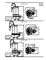
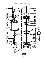
Страница 18: ...18 FIGURE 16 2SEV L 3SEV L Series Single Seal...

Страница 19: ...19 FIGURE 17 2SEV L 3SEV L Series Single Seal...

Страница 20: ...20 FIGURE 18 2SEV DS 3SEV DS Series Double Seal...

Страница 21: ...21 FIGURE 19 2SEV DS 3SEV DS Series Double Seal...

Страница 22: ...44DS 2SEV1094DS 2SEV1044DS 071354BD 3SEV1094DS 3SEV1044DS 092855BS 2SEV754L 3SEV754L 2SEV1054L 3SEV1054L 092855BD 2SEV754DS 3SEV754DS 2SEV1054DS 3SEV1054DS 068926BS 2SEV512L 3SEV512L 068926BD 2SEV512D...

Страница 23: ...27008 62 Retaining Ring All double seal 33 1 Impeller Cast Iron 3450RPM 105144TH 4 25 Dia STD for a 1 0 HP 105144TJ 4 13 Dia 105144TK 4 00 Dia 105144TL 3 88 Dia 105144TM 3 75 Dia 105144TN 3 63 Dia 105...

Страница 24: ...25 02117 Sleeve Fiberglass 66 1 030068 Jam Nut 1 2 20 SS 69 1 111909 Jumper Wire TABLE 2 POWER SENSOR CORD SETS CABLE LENGTH ITEM 16 120 VOLT 1 PHASE plug included ITEM 16 240 VOLT 1 PHASE 0 5HP plug...

Страница 25: ...25 Notes...

Страница 26: ...26 Notes...

Страница 27: ...A RETURNED GOODS AUTHORIZATION CONTACT YOUR LOCAL CRANE PUMPS SYSTEMS INC DISTRIBUTOR Products Returned Must Be Cleaned Sanitized Or Decontaminated As Necessary Prior To Shipment To Insure That Employ...

Отзывы: