background image

6

Service

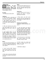
4.  With  lapped  surface  of  seal’s 
rotating  member  facing  outward, 
slide  over  shaft  using  a  seal  tool, 
being  carefull  not  to  damage  seal 
face.  Make  sure  spring  is  seated  in 
retaining  ring  and  spring  is  lined  up 
on  rotating  member  and  not  cocked 
or resting on bellows tail.

Motor:

5. Slide rotor/shaft with bearings and 
seal parts into seal plate until bearing 
seats into seal plate. Install snap ring 
into seal plate.

6.  Lower  housing  while  stringing 
motor  leads  through  the  cord  entry 
bore,  with  motor  stator  onto  seal 
plate.

7. Place screws with washers through 
housing into seal plate and torque to 
60 in/lbs.

Motor:

5. Slide rotor/shaft with bearings and 
seal parts into seal plate until bearing 
seats into seal plate. Install snap ring 
into seal plate.

Power Cord:

8.  Check  power  cord  for  cracks  or 
damage  and  replace  if  required. 
Reconnect motor leads.

9.  Place  power  cord  with  nylon 
housing,  ring,  washer  and  gland  nut 
into  housing  and  tighten  gland  nut 
to 17.5 ft/lbs.

Impeller, V-ring and Volute:

10. Position v-ring into seal plate until 
seated. 

11.  Clean  the  threads  with  thread 
locking  compound  cleaner.  Apply 
removable Loctite® 242 or equivalent 
to shaft threads. Screw impeller onto 
the  shaft  hand  tight  while  using  a 
screwdriver  in  the  slot  at  the  end  of 
the shaft to hold it stationary. Rotate 
impeller to check for binding.

12.  Position  gasket  on  volute  flange 
and  position  impeller  and  motor 
housing assembly on volute. 

13.  Place  screws  into  volute  and 
torque  to  11  ft/lbs.  Check  for  free 
rotation of impeller.

14. Refill with cooling oil.

Shaft Seal:

2.  Clean  seal  cavity  in  seal  plate  and 
oil.  Press  seal’s  stationary  member 
firmly  into  seal  plate,  use  a  seal  tool 
or  pipe.  Nothing  should  come  in 
contact with the seal face except the 
seal  tool.  Be  sure  the  stationary  is  in 
straight. 

3.  Place  seal’s  retaining  ring,  spring 
onto  shaft.  Lightly  oil  (Do  not  use 
grease)  shaft  and  inner  surface  of 
bellows.

Bearings:

1. Press bearings and onto shaft.

IMPORTANT!  -  All  parts 
must 

be 

clean 

before 

reassembly.  Handle  seal

parts  with  extreme  care.  DO  NOT 
damage lapped surfaces.

4

Reassembly

barmesa.com

Содержание BPEV512 Series

Страница 1: ...tion Operation Maintenance Manual Submersible Effluent Pumps BPEV512 series 0 5 3450 RPM IMPORTANT Read all instructions in this manual before operating or servicing a pump Last update 07 15 2021 barm...

Страница 2: ...rvicing the pump or any accessory items associatedwithornearthepump T h i s p u m p i s n o t i n t e n d e d f o r u s e i n swimming pools or water installations where there is DANGER humancontactwi...

Страница 3: ...OW16 3 sealedagainstmoisture UPPERBEARING Ball singlerow oillubricated forradialload LOWERBEARING Ball singlerow oillubricated forradialandaxialloads MOTOR NEMA L single phase permanent split capacito...

Страница 4: ...Off mode By adjusting the cord tether the control level can be changed Typical Discharge Pipe Mounted Level Control DISCHARGE VENT INLET GATE VALVE UNION CHECK VALVE Drill dia vent hole to prevent ai...

Страница 5: ...circuit relay must be used to reduce the current or the sensor will not work properly TEMPERATURE SENSOR ELECTRICAL RATINGS Volts Continuous Amperes Inrush Amperes 110 120 3 00 30 0 220 240 1 50 15 0...

Страница 6: ...e carefully inspected for leaks at the shaft seal cable assembly square ring and pipe plug before refilling with oil To locate the leak perform a pressure test After leak is repaired dispose of old oi...

Страница 7: ...hten gland nut to 17 5 ft lbs Impeller V ring and Volute 10 Position v ring into seal plate until seated 11 Clean the threads with thread locking compound cleaner Apply removable Loctite 242 or equiva...

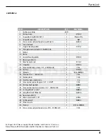
Страница 8: ...7 Repair Parts 4BPEV512 For Repair Part Please supply Model Number and Serial as shown on Name Plate and Part Description and Part Number as shown on Parts List barmesa com...

Страница 9: ...0 Rotor 1 11 Lower bearing plate 1 HT200 12 Bearing 6203 Z3 1 13 Mechanical seal 1 CC SiC 14 Impeller 1 HT200 15 Hex socket cap screws 1 4 20UNCx28 5 304 16 Casing 1 HT200 17 Handle 1 304 NBR40 18 Hex...

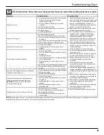
Страница 10: ...ower supply leads to ensure proper impeller rotation 11 Repair fixturesasrequiredtoeliminateleakage 12 Check pump temperature limits and fluid temperature 13 Replace portion of discharge pipe with fle...

Страница 11: ...10 barmesa com...

Отзывы: