7. Check motor capacitor (29) with an
Ohm meter by first grounding the
capacitor by placing a screwdriver
across both terminals and then
removing screwdriver. Connect Ohm
meter (set on high scale) to terminals.
If needle moves to infinity (∞) then
drifts back, the capacitor is good. If
needle does not move or moves to
infinity (∞) and does not drift back,
replace capacitor (29).
06
Service
8. Inspect motor winding for shorts
and check resistance values. Check
rotor for wear. If rotor or the stator
windings are defective, the complete
motor must be replaced.
9. Disconnect capacitor leads from
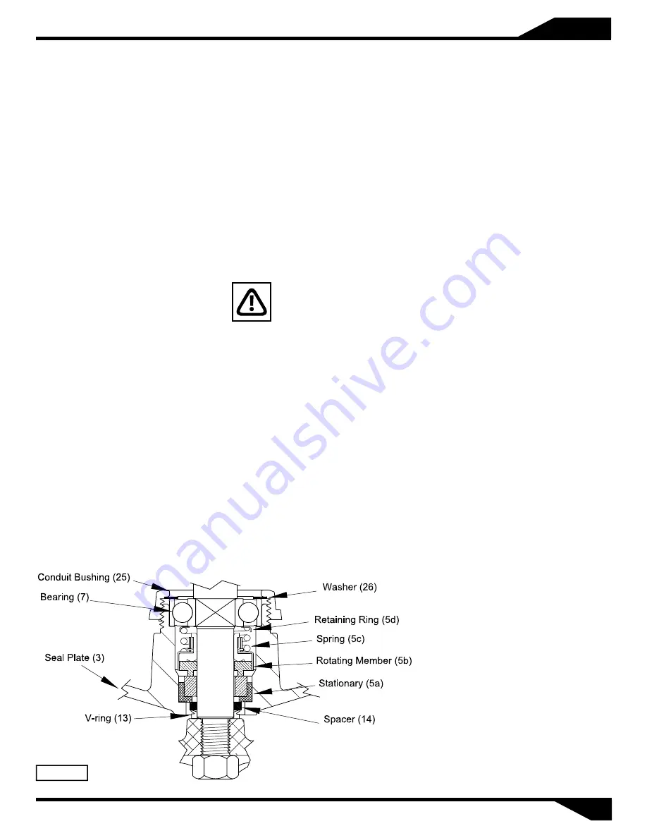
capacitor (29). Remove v-ring (13)
and spacer (14) from seal plate (3).
Remove bolts from motor stator (6)
and lift stator up from rotor. Loosen
conduit bushing (25) and remove
motor rotor, bearing and seal
assembly from seal plate (3).
Seal:
Remove rotating member (5b), spring
(5c) and retaining ring (5d), from
shaft (see Figure 3). Inspect for signs
of uneven wear pattern on stationary
member, chips and scratches on
either seal face. Replace the complete
seal if any part is damaged.
DO
NOT
interchange
seal
components, replace the entire
shaft seal (6)
. If replacing seal,
remove stationary from seal plate (3)
by prying out with flat screwdriver.
Bearing:
Examine bearing (7) and replace if
worn. Remove bearing (7) from shaft
using a wheel puller, if replacement is
required. The washer bushing (26)
and conduit bushing (25) can now be
removed.
IMPORTANT! - All parts
must be clean before
reassembly. Handle seal
parts with extreme care. DO NOT
damage lapped surfaces.
Reassembly
2. Press seal’s (5) stationary member
(5a) firmly into seal plate (3), using a
seal tool or pipe. Nothing should
come in contact with the seal face
except the seal tool. Be sure the
stationary is in straight. Lightly oil
(Do not use grease)
shaft and inner
surface of bellows.
Shaft Seal:
1. To reassemble, clean seal cavity in
seal plate (3) and oil.
Figure 3
3. Slide retaining ring (5d) and spring
(5c) over shaft and let rest on
bearing. Lightly oil (Do not use
grease) shaft, bullet and inner srface
of bellows on rotating member (5b).
See Figure 3.
4. With lapped surface of rotating
member (5b) facing outward, slide
over seal tool and unto shaft, making
sure spring (5c) is seated in retaining
ring (5d) and spring (5c) is lined up
on rotating member (5b) and not
cocked or resting on bellows tail.
5. Place conduit bushing (25) and
washer (26) onto shaft.
6. Slide rotor/shaft (6) with bearing
(7) and seal (5) into seal plate (3) until
bearing (7) seats into seal plate.
7. Locate washer (26) into place on
bearing and tighten conduit bushing
(25) onto seal plate (3).
8. Place stator (6) over rotor (6), lining
up motor bolts with holes in seal
plate (3).
9. Position capacitor (29) on motor
with clamp (30) and reconnect
capacitor leads.
10. Torque motor bolts to 17 in-lbs.
Set square ring (11) in grove on seal
plate (3).
11. Lower motor housing (4) down
onto seal plate (3) while aligning
holes and stringing motor leads
through the cord entry bore.
12. Place socket head screws (15)
through seal plate (3) into housing
(4) and torque to 60 in-lbs.
13. Reconnect motor leads, as shown
in Figure 5.
barmesapumps.com


