PRODUCT MANUAL - BARIX R6 - V01.03 - 07/20/2005
The host interface of the BARIX R6 is an RS-485 interface, which
is connectible via extension connectors as well as via screw
terminals. Besides “A” and “B” signals for the differential,
bidirectional bus signal, a third connection is available, commonly
referred to as “reference ground”. This signal is internally tied to
signal ground via a 100 Ohm series resistor.
Termination resistors are NOT provided on-board.
A termination resistor may be added at each far end of the
RS-485 bus, if required.
The BARIX R6, as well as other Barix I/O extension units, feature
soft pull-up (B) and pull down (A) of 10kOhm resistors, which
force the inactive bus to a relatively high impedance, idle
condition. Both A and B line signals are heavily protected against
ESD (Electrostatic Discharge).
Supported interface configurations are
19200 baud, 8bit, even parity, 1 stop bit (**default**)
19200 baud, 8bit, no parity, 1 stop bit
9600 baud, 8bit, even parity, 1 stop bit
9600 baud, 8bit, no parity, 1 stop bit
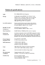
Eight LED indicators on the unit show the following conditions:
LED 1:
operating power
LED 2:
R6 answers to Modbus messages
LED 3..8:
state of the 6 output relays
The Barionet R6 contains 256 bytes of configuration memory
which can be read and (most of it) written via standard Modbus
commands. The EEPROM based memory is persistent over power
outages, no batteries are used.
Hardware
•
3
LED Indicators
RS-485
Configuration
Memory
Содержание R6
Страница 2: ......


