2 1 4
Insta
ll
at
i
on
Ho w ever w hen the d
i
fference becomes excess
i
ve
i
t may be preferab
l
e to feed the 2 po w er ports from
d
i
fferent supp
l
y vo
l
tages. The reason for th
i
s
i
s usua
ll
y to prevent h
i
gh peak vo
l
tages from be
i
ng
i
mposed on
a w
i
nd
i
ng w here the supp
l
y vo
l
tage
i
s much h
i
gher than the w
i
nd
i
ng rat
i
ng. A
l
so a w
i
nd
i
ng that w as
des
i
gned to run at fu
ll
vo
l
tage fu
ll
y phased forw ard, w
ill
be sub
j
ected to a w orse form factor w hen run
cont
i
nuous
l
y phased r
i
ght back,
l
ead
i
ng to overheat
i
ng.
The w
i
r
i
ng d
i
agram be
l
o w sho w s the preferred method of supp
l
y
i
ng the ports w
i
th d
i
fferent A C vo
l
tages.
It uses a s
i
ng
l
e phase
i
so
l
ated transformer from L2 / 3
l
eve
l
s to EL2 / 3 to su
i
t f
i
e
l
d.
E. g. The motor armature may be rated at 4 6 0 V D C to be supp
li
ed from a 4 1 5 V A C supp
l
y, and the f
i
e
l
d
vo
l
tage may be rated at 10 0 V D C, or
i
g
i
na
ll
y des
i
gned to be supp
li
ed from a rect
i
f
i
ed 1 1 0 V A C supp
l
y.
The advantages of th
i
s method are: -
1) On
l
y requ
i
res
l
o w cost eas
il
y ava
il
ab
l
e s
i
ng
l
e phase transformer.
2) The EL1/2 connect
i
ons do not suffer any phase
l
ags or
l
eads because they are st
ill
connected as per
standard schemes. Th
i
s
i
s
i
mportant because the synchron
i
sat
i
on
i
s sensed through EL1/2.
3) Th
i
s scheme w orks equa
ll
y w e
ll
for step up or do w n transformers.
4) The phase equ
i
va
l
ence of EL1/2/3 must a
l
w ays re
l
ate to L1/2/3.
5) The
i
nrush current of the transformer w
ill
probab
l
y b
l
o w the sem
i
-conductor fuses. Hence they shou
l
d be
f
i
tted on the secondary of the transformer for EL2/3. HRC fuses shou
l
d be f
i
tted
i
n the pr
i
mary feeds.
6) The f
i
e
l
d vo
l
tage requ
i
red
i
n the above examp
l
e
i
s 1 0 0 V , probab
l
y or
i
g
i
na
ll
y des
i
gned to be operated from
a rect
i
f
i
ed 1 1 0 V supp
l
y. Ho w ever w
i
th the ab
ili
ty to contro
l
the f
i
e
l
d current ava
il
ab
l
e w
i
th
i
n the PL/X,
i
t
i
s
preferab
l
e to feed the f
i
e
l
d supp
l
y w
i
th a h
i
gher vo
l
tage, e.g. 1 3 0 V . Th
i
s prov
i
des the contro
l
l
oop w
i
th a
supp
l
y marg
i
n
i
n order to contro
l
more effect
i
ve
l
y.
WA
R
N
I
NG. Th
e
f
i
e
l
d to
ea
r
th vo
l
t
a
g
e
of th
e
moto
r
must b
e
r
a
t
e
d fo
r
th
e
vo
l
t
a
g
e
a
pp
li
e
d to E
L
2
.
4) See 6.1.1 6 C ALIBR A TIO N / EL1/2/3 rated A C vo
Th
i
s must b
e
s
e
t to th
e
l
ow
e
r
of th
e
two AC vo
l
t
a
g
e
s, wh
i
c
h wou
l
d b
e
130V AC
i
n th
e
a
bov
e
e
x
a
mp
l
e
.
WA
R
N
I
NG
Th
i
s detector may then be
i
neffect
i
ve for
l
oss of EL1. Ho w ever 8.1.1 1.1 2 DRIV E TRIP MESS A GE / Synchron
oss w
ill
detect a
l
oss on EL1.
5) See 4.3 Ma
ons for deta
il
s of w
i
r
i
ng to L1/2/3 accord
i
ng to contactor requ
i
rements.
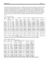
14.10 T
e
r
m
i
n
a
l
t
i
ght
e
n
i
ng to
r
qu
e
s
Term
i
na
l
s
Mode
l
T
i
ghten
i
ng torque
Term
i
na
l
s 1 to 1 0 0
PL/X 5-2 6 5
4
l
b-
i
n or 0.5 N-m
EL1 EL2 EL3 F + F-
PL/X 5-1 4 5
9
l
b-
i
n or 1.0 N-m
EL1 EL2 EL3 F + F-
PL/X 1 8 5-2 6 5
3 5
l
b-
i
n or 3.9 N-m
L1 L2 L3 A + A-
PL/X 5-5 0
3 5
l
b-
i
n or 3.9 N-m
L1 L2 L3 A + A-
PL/X 6 5-2 6 5
2 4 2
l
b-
i
n or 2 7 N-m
Fan term
i
na
l
s
PL/X 1 8 5-2 6 5
9
l
b-
i
n or 1.0 N-m
P
l
ea
s
e
a
l
so
r
e
f
e
r
to
Pa
r
t 3
PL
/X 275-980 fo
r
e
xt
r
a
d
e
t
a
il
s of f
r
a
m
e
4
a
nd 5 h
i
gh pow
e
r
d
ri
v
e
s.
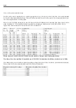
EL1
EL2
EL3
Iso
l
ated s
i
ng
l
e phase step
do w n transformer
i
s fed from
the phase equ
i
va
l
ent of L2
and L3 prov
i
des 1 3 0 V A C to
EL2 and EL3.
V A must be suff
i
c
i
ent to
supp
l
y requ
i
red f
i
e
l
d current.
3 phase supp
l
y at h
i
gh
vo
l
tage. E.g. 4 6 0 V A C.
Phased as per L1/2/3
EL1 and EL2 supp
li
ed w
i
th
4 6 0 V A C. Phase equ
i
va
l
ent
to L1 and L2, and routed
accord
i
ng to preferred
contactor arrangement.
EL2 has h
i
gh
a
nd
l
o w vo
l
tage
connect
i
ons, made poss
i
b
l
e
because the transformer
secondary
i
s f
l
oat
i
ng.
EL2/3 sem
i
-conductor fuses
f
i
tted on the secondary of
the transformer. See note 5
Содержание PLX
Страница 2: ...2 Contents ...
Страница 202: ......


