


C H A N GE PARA METERS
6 9
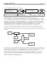
6.1.1 4 C ALIBRA TIO N / A na
l
og tacho tr
i
m PIN 1 7
Th
i
s tr
i
m factor may be app
li
ed dur
i
ng dr
i
ve runn
i
ng. The factor
i
s a
l
w ays greater than un
i
ty hence can on
l
y
i
ncrease the strength of the feedback. The c
l
osed
l
oop system then rece
i
ves feedback that
i
s too h
i
gh and
causes a reduct
i
on of the tacho vo
l
tage feedback and hence a reduct
i
on
i
n speed. (Th
i
s tr
i
m
i
s usefu
l
i
f the
prec
i
se 8)M A X T A C H O V OLTS ca
li
brat
i
on parameter
i
s not exact
l
y kno w n and must be d
i
scovered dur
i
ng
runn
i
ng by start
i
ng w
i
th a h
i
gher than expected va
l
ue. O nce the correct
l
eve
l
of feedback has been
determ
i
ned us
i
ng th
i
s tr
i
m, (mon
i
tor actua
l
l
eve
l
s of feedback
i
n the DIA G N O S TIC S menu)
i
t can then be
entered
i
n the 8)M A X T A C H O V OLTS ca
li
brat
i
on parameter and th
i
s tr
i
m returned to 1.0 0 0).
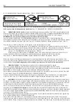
6.1.1 5 C ALIBRA TIO N / Rated armature vo
l
ts PIN 1 8 Q UIC K ST ART
Note. Th
i
s must not exceed the max
i
mum rated armature vo
l
ts def
i
ned on the motor datap
l
ate.
The armature vo
l
ts
i
s approx
i
mate
l
y proport
i
ona
l
to the motor speed.
Examp
l
e.
A motor rated at 4 0 0 vo
l
ts, 2 0 0 0 rpm,
i
s requ
i
red to run at a max
i
mum speed of 1 0 0 0 rpm.
Therefore 2 0 0 vo
l
ts w
ill
be the rated armature vo
l
ts at 1 0 0 0 rpm. Th
i
s represents 1 0 0 % speed. Note. A t
l
o w
speeds be a w are of heat d
i
ss
i
pat
i
on
i
n the motor at fu
ll
torque. Use force vent
i
ng of the motor
i
f necessary.
If des
i
red max
i
mum rpm
i
s h
i
gher than the base rpm then
i
mp
l
ement f
i
e
l
d w eaken
i
ng
i
n the C H A N GE
PAR A ME TERS / FIELD C O N TROL menu.
You must how
e
v
e
r
v
e
ri
fy th
a
t you
r
moto
r
a
nd
l
o
a
d
a
r
e
r
a
t
e
d fo
r
r
ot
a
t
i
on
a
bov
e
b
a
s
e
sp
ee
d. F
a
il
u
r
e
to do so m
a
y
r
e
su
l
t
i
n m
ec
h
a
n
i
ca
l
f
a
il
u
r
e
w
i
th d
i
s
a
st
r
ous
c
ons
e
qu
e
n
ce
s.
In
th
i
s mode the rated armature vo
l
ts
i
s usua
ll
y set to the datap
l
ate va
l
ue
i
n order to fu
ll
y exp
l
o
i
t the motor
rat
i
ngs. Further speed
i
ncrease
i
s prov
i
ded by f
i
e
l
d w eaken
i
ng and hence the armature vo
l
tage rema
i
ns
c
l
amped at the max rated va
l
ue. Th
i
s
i
s referred to
i
n the F
i
e
l
d w eaken
i
ng menu as the sp
ill
over vo
l
tage.
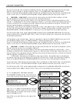
6.1.1 6 C ALIBRA TIO N / EL1/2/3 rated A C vo
l
ts PIN 1 9 Q UIC K S T ART
Note the actua
l
A C vo
l
ts may be mon
i
tored. See 7.7 DIA GN O STIC S / EL1/2/3 RMS M O N PIN 1 6 9.
The SUPPLY PH A SE LO SS a
l
arm uses th
i
s parameter to determ
i
ne the a
l
arm thresho
l
d. The
l
oss detect
i
on
thresho
l
d
i
s set at approx
i
mate
l
y 7 5 % of the vo
l
tage entered here. By enter
i
ng a vo
l
tage h
i
gher or
l
o w er than
the rated vo
l
tage
i
t
i
s poss
i
b
l
e to accomodate systems requ
i
r
i
ng detect
i
on at h
i
gher or
l
o w er thresho
l
ds.
Eg.
W
i
th 1 9)EL1/2/3 R A TED A C set to 4 1 5 V the a
l
arm w
ill
detect at 3 1 1 vo
l
ts on EL1/2/3. (7 5 % of 4 1 5 = 3 1 1)
W
i
th 1 9)EL1/2/3 R A TED A C set to 5 0 0 V the a
l
arm w
ill
detect at 3 7 5 vo
l
ts on EL1/2/3. (7 5 % of 5 0 0 = 3 7 5)
See 8.1.1 1.1 1 DRIV E TRIP MESS A GE / Supp
oss, a
l
so see 3.6 Supp
C ALIBRA TIO N 3
1 7)A N ALO G T A C H O TRIM
1 7)A N ALO G T A C H O TRIM
1.0 0 0 0
PAR A ME TER
RA N GE
DEF A ULT
PIN
A N ALO G T A C H O TRIM
1.0 0 0 0 to 1.1 0 0 0
1.0 0 0 0
1 7
Sets a pos
i
t
i
ve tr
i
m factor for
the ana
l
og tacho feedback
R
R
C ALIBRA TIO N 3
1 8)RA TED ARM V OLTS
1 8)RA TED ARM V OLTS
4 6 0.0 V D C
PAR A ME TER
RA N GE
DEF A ULT
PIN
RA TED ARM V OLTS
0.0 to 1 0 0 0.0 V OLTS 4 6 0. 0 V D C
1 8
Sets the des
i
red max armature
vo
l
tage at 1 0 0 % speed
R
R
C ALIBRA TIO N 3
1 9)EL1/2/3 R A TED A C
1 9)EL1/2/3 R A TED A C
4 1 5.0 V OLTS
Enter the 3 phase A C supp
l
y
vo
l
ts connected to EL1/2/3.
PAR A ME TER
RA N GE
DEF A ULT
PIN
EL1/2/3 RA TED A C
0 to 1 0 0 0.0 V OLTS
4 1 5. 0 V OLTS
1 9
R
R
Содержание PLX
Страница 2: ...2 Contents ...
Страница 202: ......