


M O T OR DRIV E ALARMS
1 4 5
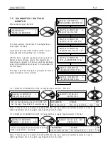
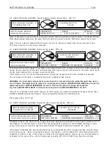
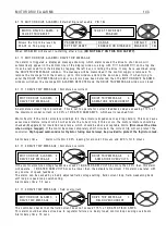
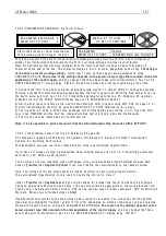
8.1.1 1. 8 DRIV E TRIP MESS A GE / Speed feedback m
i
smatch
See 8.1.1 M O T OR DRIV E AL ARMS / Speed feedback m
Th
i
s message w
ill
a
l
so appear
i
f a tr
i
p
i
s caused by try
i
ng to f
i
e
l
d w eaken w
i
th A V F feedback.
8.1.1 1. 9 DRIV E TRIP MESS A GE / Sta
ll
tr
i
p
See 8.1.8.1 ST ALL TRIP MENU / Sta
8.1.1 1. 1 0
DRIV E TRIP MESS A GE / M
i
ss
i
ng pu
l
se
See 8.1.5 M O T OR DRIV E AL ARMS / M
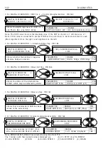
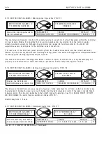
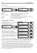
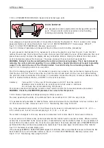
8.1.1 1. 1 1
DRIV E TRIP MESS A GE / Supp
l
y phase
l
oss
The contro
ll
er cont
i
nuous
l
y mon
i
tors the
i
ncom
i
ng supp
l
y of the EL
l
, EL2 connect
i
ons. If e
i
ther are
l
ost, the
a
l
arm w
ill
operate. The subsequent contro
l
act
i
on depends on the runn
i
ng cond
i
t
i
on at the t
i
me the a
l
arm
i
s
tr
i
ggered. The message w
ill
a
l
so br
i
ef
l
y appear after the contro
l
supp
l
y has been removed.
1) If the ma
i
n contactor
i
s energ
i
sed at the t
i
me of fa
il
ure then
i
t w
ill
be de-energ
i
sed after the r
i
de through
t
i
me of 2 seconds has e
l
apsed. If the supp
l
y
i
s restored before the r
i
de through t
i
me has e
l
apsed then norma
l
runn
i
ng w
ill
resume. Dur
i
ng the temporary supp
l
y
l
oss per
i
od the PL/X w
ill
shut the armature current demand
off unt
il
i
t
i
s safe to restore
i
t. The un
i
t measures the back emf to ca
l
cu
l
ate a safe start
i
nto the rotat
i
ng
l
oad.
2) If the ma
i
n contactor
i
s de-energ
i
sed at the t
i
me of the supp
l
y
l
oss then a Start command w
ill
a
ll
o w the
contactor to energ
i
se but
i
nh
i
b
i
t armature current. A fter a fe w seconds the contactor w
ill
be de-energ
i
sed.
The Contro
l
Supp
l
y on T 5 2, T 5 3 can to
l
erate a supp
l
y
l
oss for 3 0 0mS at 2 4 0 V A C, and 3 0mS at 1 1 0 V A C,
before request
i
ng permanent shut do w n.
See a
l
so 6.1.1 6 C ALIBR A TIO N / EL1/2/3 rated A C vo
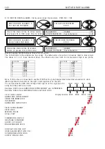
The contro
ll
er w
ill
detect tota
l
fa
il
ure of the supp
l
y. A m
i
ss
i
ng phase
i
s detected under most c
i
rcumstances.
Ho w ever, the contro
ll
er may be connected to the same supp
l
y as other equ
i
pment that
i
s regenerat
i
ng a
vo
l
tage onto the supp
l
y
li
nes dur
i
ng the m
i
ss
i
ng phase per
i
od. Under these c
i
rcumstances, the SUPPLY
PH A SE LO SS a
l
arm may be unab
l
e to detect fa
il
ure of the
i
ncom
i
ng supp
l
y, and hence not operate.
In the case of a supp
l
y phase
l
oss a
l
arm, the supp
l
y to the contro
ll
er shou
l
d be checked.
The aux
ili
ary and the ma
i
n h
i
gh speed sem
i
-conductor fuses, shou
l
d be checked.
See a
l
so 3.6 Supp
The supp
l
y
i
s mon
i
tored on EL1/2. Th
i
s a
ll
o w s A C supp
l
y or D C outgo
i
ng ma
i
n contactors to be used.
A
l
arm de
l
ay t
i
me 2. 0 secs.
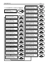
M O T OR DRIV E AL ARMS 2
DRIV E TRIP MESS A GE 3
DRIV E TRIP MESS A GE 3
SPEED FBK MIS M A T C H
M O T OR DRIV E AL ARMS 2
DRIV E TRIP MESS A GE 3
DRIV E TRIP MESS A GE 3
ST ALL TRIP
M O T OR DRIV E AL ARMS 2
DRIV E TRIP MESS A GE 3
DRIV E TRIP MESS A GE 3
MISSIN G PULSE
M O T OR DRIV E AL ARMS 2
DRIV E TRIP MESS A GE 3
DRIV E TRIP MESS A GE 3
SUPPLY PH A SE LO SS
Содержание PLX
Страница 2: ...2 Contents ...
Страница 202: ......