background image

Manual

2100-467D

Page

23 of 25

TROUBLESHOOTING  GE  ECM2.3

 MOTORS 

CONT’D.

Replacing ECM Control Module

To replace the control module for the GE variable-speed indoor blower
motor you need to take the following steps:

1. You MUST have the correct replacement module.  The controls are

factory programmed for specific operating modes.  Even though they look
alike, different modules may have completely different functionality.

USING THE WRONG CONTROL MODULE VOIDS ALL PRODUCT
WARRANTIES AND MAY PRODUCE UNEXPECTED RESULTS.

2. Begin by removing AC power from the unit being serviced.  

DO NOT

WORK ON THE MOTOR WITH AC POWER APPLIED.  

To avoid

electric shock from the motor’s capacitors, disconnect power and wait at
least 5 minutes before opening motor.

3. It is not necessary to remove the motor from the blower assembly, nor

the blower assembly from the unit.  Unplug the two cable connectors to the
motor control assembly.  There are latches on each connector.  

DO NOT

PULL ON THE WIRES.  

The plugs remove easily when properly

released.

4. Locate the screws that retain to the motor control bracket to the

sheet metal of the unit and remove them.  Remove two (2) nuts that
retain the control to the bracket and then remove two (2) nuts that
retain sheet metal motor control end plate.  

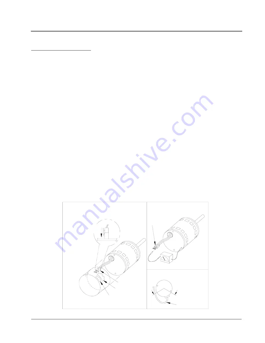
Refer to Figure 10.

5. Disconnect the three (3) wires interior of the motor control by

using your thumb and forefinger squeezing the latch tab and the
opposite side of the connector plug, gently pulling the connector.  

DO

NOT PULL ON THE WIRES, GRIP THE PLUG ONLY.  

Refer to

Figure 10.

6. The control module is now completely detached from the motor.

Verify with a standard ohmmeter that the resistance from each motor
lead (in the motor plug just removed) to the motor shell is >100K
ohms.  

Refer to Figure 11.  

(Measure to unpainted motor end plate.)  If

any motor lead fails this test, do not proceed to install the control
module.  

THE MOTOR IS DEFECTIVE AND MUST BE

REPLACED.

  Installing the new control module will cause it to fail

also.

7. Verify that the replacement control is correct for your

application.  Refer to the manufacturer's authorized replacement list.

USING THE WRONG CONTROL WILL RESULT IN
IMPROPER OR NO BLOWER OPERATION.

  Orient the control

module so that the 3-wire motor plug can be inserted into the socket in
the control.  Carefully insert the plug and press it into the socket until
it latches.  

A SLIGHT CLICK WILL BE HEARD WHEN

PROPERLY INSERTED.

8. Reverse the steps #5, 4, 3 to reconnect the motor control to the

motor wires, securing the motor control cover plate, mounting the
control to the bracket, and mounting the motor control bracket back
into the unit.  

MAKE SURE THE ORIENTATION YOU SELECT

FOR REPLACING THE CONTROL ASSURES THE
CONTROL'S CABLE CONNECTORS WILL BE LOCATED
DOWNWARD IN THE APPLICATION SO THAT WATER
CANNOT RUN DOWN THE CABLES AND INTO THE
CONTROL.

  DO NOT OVERTIGHTEN THE BOLTS.

9. Plug the 16-pin control plug into the motor.  The plug is keyed.

Make sure the connector is properly seated and latched.

10. Plug the 5-pin power connector into the motor.  Even though

the plug is keyed, 

OBSERVE THE PROPER ORIENTATION.  DO

NOT FORCE THE CONNECTOR.

  It plugs in very easily when

properly oriented.  

REVERSING THIS PLUG WILL CAUSE

IMMEDIATE FAILURE OF THE CONTROL MODULE.

11. Final installation check.  Make sure the motor is installed as follows:

a. Motor connectors should be oriented between the 4 o’clock

and 8 o’clock positions when the control is positioned in its
final location and orientation.

b.Add a drip loop to the cables so that water cannot enter the

motor by draining down the cables.  

Refer to Figure 12.

The installation is now complete.  Reapply the AC power to the
HVAC equipment and verify that the new motor control module is
working properly.  Follow the manufacturer’s procedures for
disposition of the old control module.

Motor

Motor OK when

R > 100k ohm

ECM 2.0

Only remove

Hex Head Bolts

Connector Orientation

Between 4 and 8 o'clock

Drip Loop

Back of

Control

Figure 5

Winding Test

Figure 4

Note:              
Use the shorter 
bolts and 
alignment pin 

supplied when 
replacing an 

ECM 2.0 
control.

Figure 3

ECM 

2.3/2.5

Power Connector
(5-pin)

Control Connector
(16-pin)

Hex-head Screws

Motor Connector
(3-pin)

Motor Connector
(3-pin)

Control Disassembly

Drip Loop

Push until

Latch Seats
Over Ramp

From Motor

Circuit

Board

Figure 11

Figure 10

Figure 12

Содержание PA13241-A

Страница 1: ...13361 B PA13422 A PA13422 B PA13422 C PA13482 A PA13482 B PA13482 C PA13602 A PA13602 B PA13602 C INSTALLATION INSTRUCTIONS Manual 2100 467D Supersedes 2100 467C File Volume II Tab 10 Date 08 12 08 Ba...

Страница 2: ...tings 18 Pressure Tables 19 20 Suction and Discharge Tube Brazing 21 Troubleshooting ECM Blower Motors 22 25 Figures Figure 1 Unit Dimensions 8 Figure 2 Slab Mounting at Ground Level 10 Figure 3 Airfl...

Страница 3: ...ter and Summer Air Conditioning Duct Design for Residential ACCA Manual D Winter and Summer Air Conditioning and Equipment Selection FOR MORE INFORMATION CONTACT THESE PUBLISHERS ACCA Air Conditioning...

Страница 4: ...m should be carefully read before beginning the installation Note particularly Starting Procedure and any tags and or labels attached to the equipment While these instructions are intended as a genera...

Страница 5: ...o r c S l l o r c S l l o r c S l l o r c S l l o r c S l l o r c S l l o r c S l l o r c S l l o r c S s t l o V 8 0 2 0 3 2 8 0 2 0 3 2 8 0 2 0 3 2 8 0 2 0 3 2 8 0 2 0 3 2 8 0 2 0 3 2 0 6 4 8 0 2 0...

Страница 6: ...8 4 3 1 A P C 2 8 4 3 1 A P A 2 0 6 3 1 A P B 2 0 6 3 1 A P C 2 0 6 3 1 A P 5 0 A 3 1 3 P H E 1 8 0 2 0 4 2 X X X 0 1 A 3 1 3 P H E 1 8 0 2 0 4 2 X X X 5 1 A 3 1 3 P H E 1 8 0 2 0 4 2 X X 9 0 B 3 1 3...

Страница 7: ...0 4 8 3 1 4 5 5 2 6 1 8 6 9 7 0 7 0 8 4 4 8 9 0 B 3 1 3 P H E 3 8 0 2 0 4 2 9 0 0 7 0 3 5 7 6 0 0 0 3 2 7 8 1 7 1 2 e n o N 1 4 2 8 2 5 2 0 3 0 1 0 1 0 1 5 1 B 3 1 3 P H E 3 8 0 2 0 4 2 5 1 0 0 2 1 5...

Страница 8: ...package access panel Return opening Supply opening Drain access High voltage knockout Low voltage knockout Heater package knockout L W A E B C D F A C B C H height L length W width D E F G PA PH1324 1...

Страница 9: ...All outdoor duct work must be thoroughly insulated and weatherproofed All attic duct work must be thoroughly insulated Two inch thick insulation with suitable vapor barrier is recommended for both out...

Страница 10: ...re Condenser fan and motor access from top Leave 60 min above fan Side View Top View MIS 2143 between duct and any combustible material if distance between outside wall and unit is less than 3 feet ne...

Страница 11: ...48 min 32 F or lower climate 12 min if in on surface of platform Both legs must rest 48 min 32 F or lower climate 12 min if in on surface of platform Both legs must rest Metal frame MIS 2144 Platform...

Страница 12: ...w for expansion of water when it freezes AIR FILTERS Air filters for the return air side of the system are not provided as part of these models and must be field supplied and installed as part of the...

Страница 13: ...l The electrical specifications list fuse and wire sizes 75 F copper for all models including the most commonly used heater sizes The unit rating plate lists a Maximum Time Delay Fuse or HACR type cir...

Страница 14: ...Y Terminal R G C HEAT ON UNITS WITH 15 OR MORE KW C Low Voltage Wiring B R W RC R Y1 L G C G Block R E Y L Thermostat Subbase 3 1 2 W1 W2 F RC B Unit 24V REMOVE JUMPER FOR 2 STAGE ELECTRIC B YO 1120...

Страница 15: ...recharges R 410A refrigerant is close to being an azeotropic blend it behaves like a pure compound or single component refrigerant The remaining refrigerant charge in the system may be used after leak...

Страница 16: ...sor operation is inhibited If a fault condition occurs reverse tow of the supply leads to the unit Do not reverse any of the unit factory wires as damage may occur SEQUENCE OF OPERATION BLOWER ONLY Wh...

Страница 17: ...never compressor is locked out due to HPC or LPC sequences as described NOTE Both high and low pressure switch controls are inherently automatic reset devices The high pressure switch and low pressure...

Страница 18: ...he correct system R 410A charge is shown on the unit rating plate You can reference Tables 10 11 to validate proper system performance However it is recommended that if incorrect charge is suspected t...

Страница 19: ...4 7 2 0 4 1 6 9 2 2 4 1 8 1 3 4 4 1 0 4 3 7 4 1 2 6 3 9 4 1 4 8 3 1 5 1 2 1 4 3 5 1 0 4 4 6 5 1 9 6 4 8 5 1 7 9 4 0 6 1 5 2 5 2 6 1 3 5 5 5 8 B D 2 7 B W e d i S w o L e d i S h g i H 5 4 1 1 6 2 8 4...

Страница 20: ...4 7 3 1 5 6 4 9 3 1 2 9 4 0 4 1 0 2 5 2 4 1 7 4 5 0 8 B D 7 6 B W e d i S w o L e d i S h g i H 4 3 1 5 4 2 5 3 1 0 7 2 7 3 1 4 9 2 8 3 1 9 1 3 9 3 1 4 4 3 1 4 1 8 6 3 2 4 1 3 9 3 4 4 1 1 2 4 5 4 1 9...

Страница 21: ...2 and 3 slowly and uniformly until braze material softens and the tube can be pulled out of suction fitting See Figure 9 To connect Recommended brazing materials silfos with minimum 5 silver or silver...

Страница 22: ...sive noise Determine if it s air noise cabinet duct or motor noise interview customer if necessary Air noise High static creating high blower speed Is airflow set properly Does removing filter cause b...

Страница 23: ...er to the manufacturer s authorized replacement list USING THE WRONG CONTROL WILL RESULT IN IMPROPER OR NO BLOWER OPERATION Orient the control module so that the 3 wire motor plug can be inserted into...

Страница 24: ...ry d Check the external static pressure total of both supply and return to insure that you are within the ranges as listed on the unit serial plate If higher than allowed additional duct work is neede...

Страница 25: ...nd the appropriate motor terminal 1 5 G input is typically on terminal 1 but refer to wiring diagram a If the low voltage communication is not present check the demand from the thermostat Also check t...

Отзывы: