background image

Manual 2100-670B 

Page 

22 of 33

Compressor

Compressor Components

Compressor

Three Phase Scroll Compressor Start Up Information

Scroll compressors, like several other types of 
compressors, will only compress in one rotational 
direction. Direction of rotation is not an issue with 
single phase compressors since they will always start 
and run in the proper direction.
However, three phase compressors will rotate in either 
direction depending upon phasing of the power. 
Since there is a 50-50 chance of connecting power 
in such a way as to cause rotation in the reverse 
direction, verification of proper rotation must be made. 
Verification of proper rotation direction is made by 
observing that suction pressure drops and discharge 
pressure rises when the compressor is energized. 
Reverse rotation also results in an elevated sound level 
over that with correct rotation, as well as substantially 
reduced current draw compared to tabulated values.
Verification of 

proper rotation

 must be made at the time 

the equipment is put into service. If improper rotation 
is corrected at this time, there will be no negative 
impact on the durability of the compressor. However, 
reverse operation for over 1 hour may have a negative 
impact on the bearing due to oil pump out.

NOTE:

 If compressor is allowed to run in reverse 

rotation for an extended period of time, the 

compressor’s internal protector will trip.

All three phase compressors are wired identically 
internally. As a result, once the correct phasing is 
determined for a specific system or installation, 
connecting properly phased power leads to the same 
Fusite terminal should maintain proper rotation 
direction.
The direction of rotation of the compressor may be 
changed by reversing any two line connections to the 
unit.

Compressor Control Module (CCM)

The compressor control module is a low voltage 
monitoring device necessary to monitor power and 
indicate a low incoming voltage situation caused by 
inadequate shore power or generator operation. The 
monitoring device protects the unit against compressor 
contactor “chatter” and reverse compressor rotation 
during these situations. 
Compressor protection device has an adjustable 
30-second to 5-minute timer (red-dial). This module 
features a delay-on-make for initial start up (or anytime 
power is interrupted) for a minimum 2 minutes plus 
10% of the red-dial setting. There is no delay during 
routine operation of the unit. The compressor control 
module also monitors the high pressure switch, and 
will allow one automatic retry (after soft lockout delay) 
before disabling the compressor in a hard lockout 
(requires manual reset). If hard lockout does occur, 
the ALR terminal on the CCM will become active with 
24v, which will power the high pressure relay within 
the wall unit. The relay contacts are monitored by the 
unit controller. If the CCM indicates an alarm to the 
wall unit controller, an alarm will be generated and the 
compressor will be locked out by the controller. 

NOTE:


The controller will remove cooling call on the Y 

terminal of the CCM, reseting it almost instantly. 

The compressor remains locked out by the 

controller until manually cleared.

Switch is jumpered in this application. Instead, the low 
pressure transducer is used for low pressure monitoring.

High Pressure Safety Switch

All units have a high pressure switch as a safety device. 
This device will open when pressure in the system 
reaches 650 PSIG. The sensor is directly connected to 
the dedicated compressor control module. This module 
will disable any call for cooling if the pressure is above 
this limit. If tripped, the high pressure switch can be 
reset by turning the output off and then back on again.

Refrigerant High Pressure Alarm

When the wall unit receives a signal from the 
compressor control module (CCM) indicating a high 
pressure event, the wall unit will generate an alarm. 
Upon receiving the alarm, the wall unit will remove 
the “Y” call from the CCM, resetting the status of the 
CCM. The alarm will stay present on the wall unit until 
manually cleared.
Alarm index numbers: 21, 40, 55, 70
In addition to the CCM, the discharge pressure 
transducer is used to prevent a high pressure event. 
When the discharge pressure is above the discharge 
pressure alarm setpoint (set 30 pounds below high 
pressure switch, which is 650), the system will disable 
stage 2 of mechanical cooling.
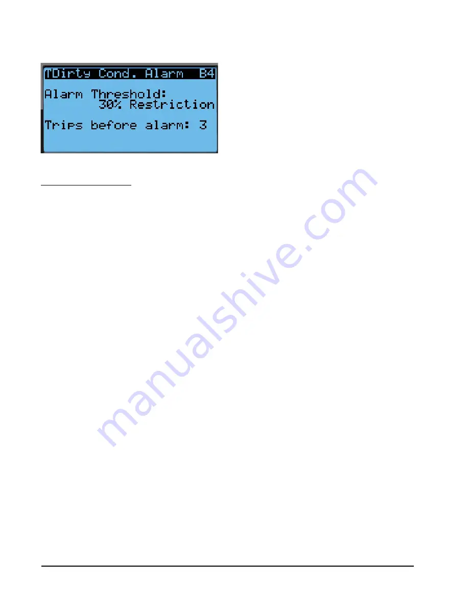
FIGURE 29

Adjusting Dirty Condensor Coil Alarm Settings

Содержание FUSION-TEC HR36APA

Страница 1: ...om Manual 2100 670B Supersedes 2100 670A Date 9 22 17 NOTE LV1000 Controller is required for operation when multiple HR AP units are used SERVICE INSTRUCTIONS FUSION TEC WALL MOUNT AIR CONDITIONER Models Part of the Bard Free Cooling Unit System HR36APA HR36APB HR58APA HR58APB ...

Страница 2: ...w Operation 18 Blower Speed Control 18 Additional Indoor Airflow Alarms 18 Supply Air Temperature Alarm 18 Condenser Fan 18 Condenser Fan Components 18 Condenser Fan 18 Liquid Line Pressure Transducer 19 Troubleshooting the Discharge Liquid Pressure Transducer 20 Discharge Liquid Pressure Transducer Alarm 20 Liquid Temperature Sensor 20 Condenser Fan Operation 20 Condenser Fan Speed Control 20 Hig...

Страница 3: ...irty Filter Switch Filter Indicator Light 17 Figure 21 Verifying Freeze Switch Status 18 Figure 22 Adjusting Freezestat Alarm Delay 18 Figure 23 Verifying Condenser Fan Output 19 Figure 24 Fan Blade Setting 19 Figure 25 Adjusting Discharge Liquid Transducer Pressure Values 19 Figure 26 Voltage to Pressure Discharge Liquid Pressure Transducer 20 Figure 27 Adjusting Discharge Liquid Temperature Inpu...

Страница 4: ...is made See Additional Publications for information on codes and standards Sizing of systems for proposed installation should be based on heat loss and heat gain calculations made according to methods of Air Conditioning Contractors of America ACCA The supply flange should be installed in accordance with the Standards of the National Fire Protection Association for the Installation of Air Conditio...

Страница 5: ...is to be limited to the most extreme situations DANGER signs should not be used for property damage hazards unless personal injury risk appropriate to these levels is also involved WARNING Indicate s a hazardous situation which if not avoided could result in death or serious injury WARNING signs should not be used for property damage hazards unless personal injury risk appropriate to this level is...

Страница 6: ... in case of power failure The controller is designed to manage temperature levels to a user defined setpoint via control output signals to the wall mount air conditioning system The TEC EYE connects to the wall mount unit control board via an RJ11 modular phone connector as shown in Figure 2 ALARM KEY Allows viewing of active alarms Silences audible alarms Resets active alarms MENU KEY Allows entr...

Страница 7: ...nu is accessible from the Status screen Setpoints Information and Data Alarm Log are available through the Quick Menu Pressing the UP or DOWN keys while on the Status screen will change the Quick Menu icon displayed see Figure 3 Press the ENTER key when the desired icon is displayed Quick Menu Setpoints From this screen the unit heating and cooling setpoints can be changed The LV1000 setpoints wil...

Страница 8: ...s and program version information Data Alarm Log The alarm log screens show a log of each alarm There will be a log for when alarm occurred and if the alarm auto clears it will show when the alarm cleared Menu Screens and Password Levels A System Config A1 A10 User B Adv Sys Config B1 B4 Technician C I O Config C1 C18 Technician D On Off User E Alarm Logs User F Settings Date Time Technician Langu...

Страница 9: ...in each wall mount unit In stand alone mode the wall unit uses a continuous blower setting to circulate room air into the return air inlet and uses the return air temperature sensor to control room temperature The wall mount unit can be turned on and off with the TEC EYE hand held diagnostic tool When ON is chosen the wall unit will heat or cool The blower will continue to run when OFF is chosen I...

Страница 10: ...ntrol will compare the space temperature to the space setpoint Based on how far away from the setpoint the temperature is the loop will output a cooling or heating capacity number between 0 and 100 The unit will then take all of the available cooling methods and distribute them evenly across the 0 100 range The stages are then brought on as the heating or cooling capacity reaches the percentage th...

Страница 11: ...e for economizer operation so there are a total of 2 cooling stages see Figure 9 Heating The unit is equipped with 1 stage of electric heat see Figure 10 Staging The unit will stage the cooling components based on the cooling demand referenced in the temperature control The unit will stage the economizer on first if the indoor and outdoor conditions are favorable The compressor stage 1 will be ena...

Страница 12: ...ulation that determines the EEV position This sensor can be verified and adjusted by 1 Press MENU key to go to the Main Menu screen 2 Press UP or DOWN keys and ENTER key to enter TECHNICIAN password 1313 3 Press UP or DOWN keys to scroll to I O Config press ENTER key 4 Press UP or DOWN keys to scroll to Suction Pr Sensor C11 press ENTER key 5 Verify the measurement displayed on screen is accurate ...

Страница 13: ...ice or troubleshooting FIGURE 14 Overriding EEV Output FIGURE 13 Adjusting Suction Temperature Sensor Values The valve can be positioned by using a menu override To manually override the valve NOTE The unit must be off to perform this override 1 Press MENU key to go to the Main Menu screen 2 Press UP or DOWN keys and ENTER key to enter TECHNICIAN password 1313 3 Press UP or DOWN keys to scroll to ...

Страница 14: ...otor ECM This blower is controlled by a 0 10v signal provided from the controller This 0 10v signal is converted to a PWM signal with an adapter The blowers on both the HR36AP and HR58AP models use a 10 diameter wheel The HR36AP operates between 250 850 rpm while the HR58AP operates between 250 1400 rpm The blower output can be put into an override mode for verification or troubleshooting To put t...

Страница 15: ...800 1400 0 10 TABLE 5 Indoor Blower Performance Speed High Low ESP Inch H20 Dry Coil Wet Coil Dry Coil Wet Coil HR36AP 0 00 1260 1200 995 950 HR58AP 0 10 1885 1800 1470 1400 TABLE 6 Maximum ESP of Operation Electric Heat Only Unit is rated for free blow non ducted operation with SGR 5W Supply Grille and RGR 5W Return Grille Model Static Pressure A0Z A05 00 00 B0Z B06 00 00 Blower Status Alarm If t...

Страница 16: ...ference across the filter through silicone tubing routed to the blower and vent areas of the unit The switch circuit consists of a normally open filter pressure switch The switch will open when the pressure differential goes above the setting indicated on the dial When the pressure difference returns below the setting on the dial the switch will close Adjustment of dirty filter switch may be neces...

Страница 17: ... 0 30 Evaporator Airflow 100 99 3 99 4 98 8 97 3 91 5 89 8 88 3 HR58AP Default High S T Switch Static Setting 0 40 0 50 0 60 0 70 0 75 0 80 0 90 1 00 Evaporator Airflow 100 98 7 98 1 97 5 91 7 81 3 79 1 78 6 HR58AP Standard Airflow Switch Static Setting 0 30 0 35 0 40 0 45 0 50 0 65 0 70 0 90 Evaporator Airflow 100 99 8 99 98 5 96 8 89 9 84 82 2 All units tested equipped with MERV 8 filters Approp...

Страница 18: ...e high sensible command from LV please see LV1000 Service Instructions 2100 673 Additional Indoor Airflow Alarms Supply Air Temperature Alarm When the supply air temperature sensor value is out of range 41 0 to 303 0 F the controller will generate a sensor failure alarm to indicate the sensor is not working properly This alarm is fixed and cannot be adjusted Condenser Fan Condenser Fan Components ...

Страница 19: ...Should a change of motor or fan blade be necessary see Figure 24 for proper clearance adjustment Liquid Line Pressure Transducer The unit has a pressure transducer installed on the liquid line between the condenser and electronic expansion valve EEV The transducer is used for system monitoring of the liquid side system pressures FIGURE 24 Fan Blade Setting 75 This information is used to indicate w...

Страница 20: ...ey 4 Press UP or DOWN keys to scroll to Disch Temp Sensor C3 press ENTER key 5 Reference the Value to verify the temperature see Figure 27 6 If an offset needs to be applied press ENTER key to scroll to Offset 7 Press UP or DOWN keys to change the offset to desired value 8 Press ENTER key to save 9 Press ESCAPE key several times to return to Main Menu screen Condenser Fan Operation Condenser Fan S...

Страница 21: ...mum speed continuing the previously discussed cycle Additional Condenser Fan Alarms Dirty Condenser Coil Alarm The unit will continuously monitor system conditions to determine if the condenser coil is dirty or blocked FIGURE 28 Condenser Fan Pressure Control If the system monitors three consecutive cooling cycles that indicate a dirty condenser coil an alarm will be generated This alarm is a noti...

Страница 22: ...tion during these situations Compressor protection device has an adjustable 30 second to 5 minute timer red dial This module features a delay on make for initial start up or anytime power is interrupted for a minimum 2 minutes plus 10 of the red dial setting There is no delay during routine operation of the unit The compressor control module also monitors the high pressure switch and will allow on...

Страница 23: ...or operation If a fault condition occurs reverse two of the supply leads to the unit Do not reverse any of the unit factory wires as damage may occur Compressor Operation The compressor will be enabled when the unit in stand alone mode or LV provide a cooling stage 1 call The compressor call from the controller has several delays that may affect the start or stop time of the compressor in regards ...

Страница 24: ...l update with the new override value and the damper will travel to that position NOTE This override will last for 5 minutes or until the Override is changed back to Disabled Dust Sensor The unit has a dust sensor installed near the outdoor air inlet The dust sensor checks for excessive particulates in the outdoor air and will close the economizer if the dust is excessive The sensor uses a PWM sign...

Страница 25: ...ty to cool Damper Blade The system utilizes three damper blades used to bring in outdoor air and exhaust space air for economizer operation The damper blades are made of sheet metal and are integrated into the equipment Damper Switch The economizer utilizes a magnetic switch to determine if the damper is operating correctly This switch will be closed when the damper is closed and open when the dam...

Страница 26: ...it is equipped with a combination outdoor temperature and humidity sensor to monitor outdoor conditions for the economizer operation The temperature is measured with a 10k ohm NTC FIGURE 36 Adjusting Damper Alarm Delay thermistor The humidity is measured with a humidity sensor that outputs a 4 20mA signal to the controller The outdoor temperature can be verified by 1 Press MENU key to go to the Ma...

Страница 27: ...ensor Outdoor Temperature Sensor Failure Alarm When the sensor reads a value that is outside of the acceptable 41 to 303 0 range an alarm will be generated indicating the sensor has failed This alarm condition will disable the economizer This alarm is fixed and cannot be adjusted Alarm index numbers 11 30 45 60 Outdoor Humidity Sensor Failure Alarm When the sensor reads a value that is outside of ...

Страница 28: ... Enthalpy where the outdoor temperature humidity and calculated dew point are considered for economizer operation on a cooling call To change the economizer type 1 Press MENU key to go to the Main Menu screen 2 Press UP or DOWN keys and ENTER key to enter USER password 2000 3 Press UP or DOWN keys to scroll to System Config press ENTER key 4 Press UP or DOWN keys to scroll to Economizer Setup A2 p...

Страница 29: ...e actuator The actuator will then open and close the damper blades to maintain a mixed air temperature of 55 F When the mixed air temperature increases the damper will open and when the mixed air temperature decreases the damper will close The economizer may be disabled by the LV if the system determines it needs to enter dehumidification mode More information about the dehumidification sequence c...

Страница 30: ... has the option to be shipped from the factory with a low pressure switch panel sensors and a speaker These devices are used with the Bard Guard BG1000 anti theft controller to provide an anti theft measure These sensors and switch form a loop that when connected to the BG1000 controller will cause the system to go into alarm if any of the front panels or coil assemblies are removed without being ...

Страница 31: ...rigerant it must come out of the charging cylinder tank as a liquid to avoid any fractionation and to insure optimal system performance Refer to instructions for the cylinder that is being utilized for proper method of liquid extraction Safety Practices 1 Never mix R 410A with other refrigerants 2 Use gloves and safety glasses Polyol ester oils can be irritating to the skin and liquid refrigerant ...

Страница 32: ... 318 130 340 131 365 132 389 133 414 134 440 136 467 137 495 137 527 139 553 140 584 80 67 Low Side High Side 138 326 139 349 140 374 141 399 142 425 143 451 145 479 146 508 147 537 149 567 150 599 85 72 Low Side High Side 143 337 144 361 145 387 146 413 147 440 148 467 150 496 151 526 152 556 154 587 155 620 Part Load Cooling Air Temperature Entering Outdoor Coil F Model Return Air Temp DB WB Pre...

Страница 33: ... an individual unit to be disconnected from the Bard Guard security system for an extended period of service time longer than the maximum 250 minutes disarm time place a jumper across the appropriate terminals on the BG1000 terminal block to temporarily remove the unit from the security system Be sure to remove the jumper from the terminals after service has been completed See the latest revision ...

Отзывы: