background image


86 

10.  BUTTON REPLACEMENT 


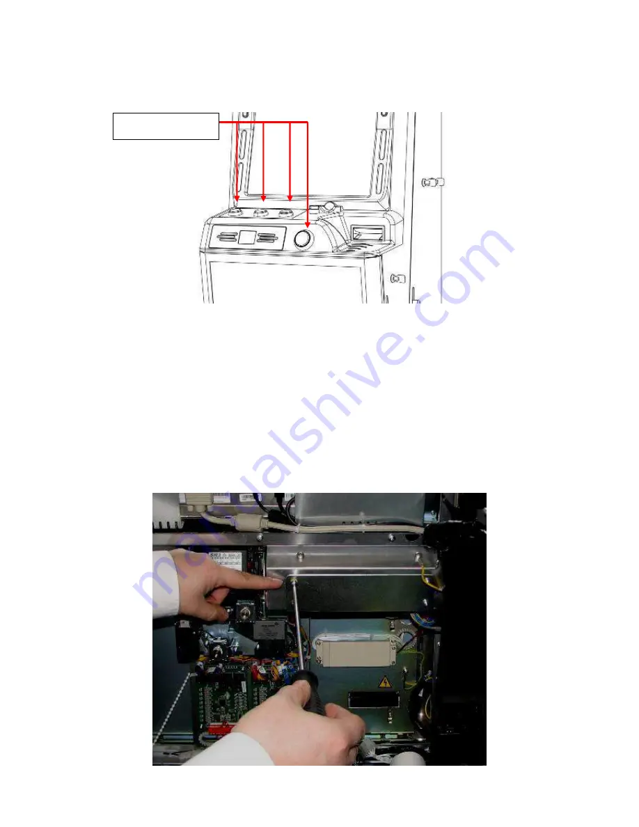
The Triple 7 cabinet is fitted with 4 game buttons as shown in the diagram below.  


These buttons are powered from the right hand side LED driver PCB as previously described in 
section 9. 


In the event of a button failure, it is advisable to check that the driver board has not failed. This 
can be achieved by simply swapping the boards over. If the fault remains the problem lies with 
the Button itself. To replace the smaller upper buttons the following instructions must be 
followed. 
 

1.  Power down the machine 
 
2.  Unscrew the internal plate as shown below 


Game Play Buttons 

Содержание Triple 7 MPU6

Страница 1: ...1 F FI IE EL LD D S SE ER RV VI IC CE E M MA AN NU UA AL L M MP PU U6 6 B BA AS SE E I IS SS SU UE E 2 2 2 2...

Страница 2: ...Top Box PSU fitting instructions V1 5 09 04 10 Additional information added for infill cables V1 6 27 07 10 SR3e encryption installation instructions added V1 7 09 06 11 Coin and note mech additional...

Страница 3: ...LL PANEL INSTALLATION 17 3 5 TOP BOX AND INFILL POWER SUPPLY FITTING INSTRUCTIONS 19 4 I BUTTON DALLAS KEYS 21 5 INITIAL POWER UP 22 5 1 MAIN MENU 22 5 2 EVENT LOGS 23 5 3 SYSTEM INFORMATION 25 5 4 SO...

Страница 4: ...MECH REMOVAL 68 6 3 SR3e ENCRYPTION KEY RESET 68 6 4 REPLACEMENT ENCRYPTED COIN MECH SET UP 69 6 5 SERIAL DEVICES SET UP 69 7 NOTE ACCEPTOR INFORMATION 71 7 1 NV11 NOTE ACCEPTOR MAINTANANCE 75 7 1 1 N...

Страница 5: ...96 SR3e ENCRYPTED COIN MECH 96 HOPPER ASSEMBLY No Hoppers 96 10P COMPACT HOPPER 96 SERIAL UNIVERSAL HOPPER 96 TRI COLOUR LED PCB 96 LED 6 DRIVER PCB 96 MPU6 96 START DISCO BUTTON 96 COLLECT BUTTON 96...

Страница 6: ...game operators and service personnel Specific warnings and cautions will be found throughout this manual where they apply We recommend that you read these pages before preparing your Triple 7 s cabine...

Страница 7: ...nnector at one end and an approved 13 amp plug fitted with a 5 amp fuse at the other In the case of non fused power cords an approved and suitably rated Residual Current Device shall be used INSULATIO...

Страница 8: ...is located on the printed circuit board It s location is obvious upon removing the plastic case of the MPU and it may be easily removed without the aid of a tool The PC also contains a similar batter...

Страница 9: ...printer Separate door opening with high security multipoint locking system MPU5 6 as intelligent input output interface Ardac Elite Note Acceptor to casino standards Card reader and ticket printer TIT...

Страница 10: ...Y BEZEL BELLY GLASS DOOR RELEASE LEVER MAIN DOOR OUTER CASH DOOR CASH PAYOUT TRAY GAME SPECIFIC BUTTONS 19 LCD TOUCHSCREEN MONITOR 19 LCD MONITOR SPEAKER SPEAKER TRIPLE 7 s MAIN EXTERNAL COMPONENTS VI...

Страница 11: ...SUPPLY DISTRIBUTION UNIT TICKET PRINTER WHERE USED INDUSTRIAL PC UNIT MPU6 UNIT NOTE ACCEPTOR STACKER PAYOUT ASSEMBLY MAIN DOOR SWITCH CASH DOOR SWITCH NOTE ACCEPTOR STACKER LOCK CASH BOX DOOR BARBUS...

Страница 12: ...tribution Board Ticket Printer When Fitted Card Reader When Fitted Door Switches x 3 Main Belly Glass Bottom Doors I Button Dallas Technology Receptors Ports x 3 Check to see that all components and c...

Страница 13: ...hting The machine should be positioned where site staff can supervise it The machine should not be moved when the door is open failure to adhere to this may result in the machine failing over causing...

Страница 14: ...lift away the cover plate Carefully lift the Top Box to the top of the cabinet and feed the wiring through the large centre hole Align the Top Box bolts with the holes that are situated either side o...

Страница 15: ...fitted using the 4 x M6 bolts supplied as shown in the image below Remove the cover plate from the top of the cabinet by removing the 4 x M6 nuts from the inside of the cabinet as indicated in the ima...

Страница 16: ...be secured to the cabinet using the wing nuts supplied Once secured the cables can now be connected The Video Top Box Barbus cable is connected to the Barbus Distribution board as shown in image 1 be...

Страница 17: ...4 x Securing Brackets 3 12 x M6 Bolts Barcrest recommends the minimum of two people for the installation of the Triple 7 infill unit 1 Ensure the 240V mains supply is disconnected from the cabinet be...

Страница 18: ...e second braided sync cable is now fed into the second machine and is connected into one of the spare sockets available on the Barbus distribution PCB interface and so on for each infill panel ensurin...

Страница 19: ...anels have not been installed then please refer to the fitting instructions in Section 3 4 3 For each machine open up the top and bottom doors to gain access to the inside of the machine and then disc...

Страница 20: ...m of the cab as shown in the second image below 7 Locate the Sentronics power supply into the base of the cabinet and connect up the connectors from the PSU and extension link as shown in the first im...

Страница 21: ...tion 5 7 Customer Collections for further information When the I Button is presented to the external receptor with all the doors closed it will allow access to the managers refill screen Please refer...

Страница 22: ...initialisation with no problems encountered and the machine in a Door Open state the screen will display Main Menu 5 1 MAIN MENU On opening the main service or cash door you are presented with the mai...

Страница 23: ...automatically display the Operator Log The Operator Log details all cash in and out events any operational percentage stakes and prize changes and all technical related occurrences such door status a...

Страница 24: ...he machine information which can then be analysed at Barcrest To perform this task the following instructions must be followed From the Technical Log section press Dump Logs You will now be prompted t...

Страница 25: ...e facility to easily view the installed software and hardware versions 5 4 SOFTWARE VERIFICATION Software Verification can be accessed via the System Information screen this facility is used to ensure...

Страница 26: ...g your new game you must first check the contents within the kit USB Game Key USB Game Licence Key Game Update Instructions Game Licence Update Instructions USB Game Licence Key return sticker Once th...

Страница 27: ...w Once the USB licence key has been inserted there will be a short pause while the game licence is installed Following a successful installation the user will be informed that the new licence has been...

Страница 28: ...as shown in the image below The installation is now complete To ensure the game has been correctly installed and licensed close all the machine doors Following a reset the newly installed game should...

Страница 29: ...appropriate button Detailed Accountancy The detailed button when selected from the accountancy screen shows detailed metering information for each game The metered information is accompanied with the...

Страница 30: ...e screen as shown below 1 Other Amount 2 10 00 value may differ dependant on machine category and hopper configuration 3 20 00 value may differ dependant on machine category and hopper configuration 4...

Страница 31: ...set to the customer specifications within the Terminal Configuration section Please refer to section 5 14 Terminal Configuration for more information Accountancy The Accountancy information is covere...

Страница 32: ...the machine volume level By selecting the Set Volume Toggle Button the screen will now display a slider By moving this slider to the left will decrease the volume and by moving it to the right will in...

Страница 33: ...automatically copy the selected file s from the USB key on to the machine ready for configuration please refer to section 5 11 CONFIGURATION When the file transfer process has been completed the machi...

Страница 34: ...t three stages detail this process INSTALLING THE GAME From the main menu screen select Config then select the Game Configuration button The following screen titled Games will now be displayed on the...

Страница 35: ...nto game slot 5 the install arrow icon indicated below would need selecting ENABLING THE GAME To enable the game select the enable icon as indicated in the image below to change the enabled message fr...

Страница 36: ...ated in the image below in the games menu Once the config arrow icon has been selected the lower screen will display the current settings applicable to the installed game The operator may change these...

Страница 37: ...mes button The following screen titled Themes will now be displayed on the lower monitor On selection of the Load icon the lower monitor will now display all available Themes that have been previously...

Страница 38: ...38 By selecting the Yes button the selected Theme will now automatically load Once the chosen Theme has successfully loaded it will now be displayed as the default Theme...

Страница 39: ...following functions may be adjusted Volume Adjust The volume level is controlled via the slider bar By moving this slider to the left will decrease the volume and by moving it to the right will increa...

Страница 40: ...fig screen The machines details such as machine name address etc can be added through the touch screen by selecting the icon to the left hand side of the text Each line of the machine detail and addre...

Страница 41: ...adjusted Cash Limits By selecting Cash Limits from the Operator Config screen the user will be able to view the current set bank and credit limits including direct pay settings Operator Category By se...

Страница 42: ...ht to increase or alternatively the or icons may be used By selecting the enable icon the tick symbol will change to a cross at this point the note acceptor will be disabled Payout Devices By selectin...

Страница 43: ...en the note payout unit must be emptied into the stacker using the dump hopper button procedure as described in the collection procedure in section 5 7 When the note payout configuration button is sel...

Страница 44: ...placed into the hopper The divert level is the maximum number of coins allowed in the hopper before coins are diverted to the cash box Hand Pay Hand Pay enables operator the facility to pay any winni...

Страница 45: ...n located and verified the service screen will be displayed on the bottom screen The Service menu enables the operator the facility to test individual components within the cabinet these functionality...

Страница 46: ...of the screen edges and or don t have equal borders press the Source Button located on the rear of the LCD display To check for failed pixels continue to touch the screen and step through each of the...

Страница 47: ...MPU Select the update MPU button to update the MPU6 binary file as required The option for the appropriate data port and standard binary file can be selected from this screen as shown in the screen s...

Страница 48: ...e Touchscreen test button from the service menu to enter the Touchscreen calibration screen Select the red buttons on the Touchscreen to calibrate Now select the flashing start button to accept the ca...

Страница 49: ...he bottom monitor for reference By selecting the Flash LEDs button the machine will illuminate all LEDs within the cabinet On selection of the Manual Step LEDs button the user can step through each LE...

Страница 50: ...re functioning correctly Once a coin or note has been inserted and accepted the appropriate monetary value will be displayed on the bottom monitor as shown below The divert button allows the operator...

Страница 51: ...are entered by selecting the serial number entry icons indicated in the image below One the appropriate codes have been entered then select the relevant set up icon Once selected an icon will appear...

Страница 52: ...oning correctly On entering the screen the operator will be presented with four on screen buttons These buttons allow the user to pay an individual coin or a multiple of 20 coins if selected The value...

Страница 53: ...as appropriate Start Test button to repeat the test Dataport Test On selecting Dataport Test the machine will proceed to test the Dataport interface A Dataport compliant device must be connected to t...

Страница 54: ...oard The MPU 6 board offers numerous enhancements from its reliable robust MPU5 ancestor these include an integrated on board 16 character LCD display with backlight and menu buttons increased process...

Страница 55: ...prox 10 seconds power up the cabinet the new software will now be loaded In the event that the MPU6 requires a full reset a Clear Down USB stick will be required from Barcrest After Sales and the foll...

Страница 56: ...nd serial data link connected in a daisy chain layout between the machine modules The Barbus is connected to the MPU6 board via a red 11 way BARBUS connector S P DIF Input The S PDIF interface Sony Ph...

Страница 57: ...st digit of the Barcrest alarm number shows the class of alarm A complete list of alarm messages related to the associated BACTA and Barcrest fault code numbers are shown in the following sections Cla...

Страница 58: ...age 53 21 RAM TEST FAILED 54 22 BARBUS FAILED 54 22 CPU PIT FAILED 54 22 CPU UART FAILED 54 23 MPU6 UART FAULT 54 24 ASIC TEST FAILED 54 25 MSP430 FAILED 54 2A METER SENSE FAIL 54 2A LCD METER FAIL 54...

Страница 59: ...Jam 81 70 Coin Mech Fail 14 71 5p Coin Timing 14 72 5p Coin Locked 14 73 10p Coin Timing 14 74 10p Locked Out 13 75 20p Coin Timing 13 76 20p Locked Out 12 77 50p Coin Timing 12 78 50p Locked Out 11 7...

Страница 60: ...ut alarms procedural events BACTA Code Barcrest Code Message 41 D1 REFILL TURNED 45 D2 NEW OPTIONS 47 D3 REFILL NEEDED 40 D4 DOOR NOT LOCKED 40 D5 DOOR LOCKED Class E alarms Class E alarms relate to c...

Страница 61: ...so that they support the PC case prior to removal 4 Loosen off the two M4 nuts that fix the bottom of the PC in position indicated in the image below as these will be needed to support the PC prior t...

Страница 62: ...62 The following diagram details the connections to the PC all connectors must be fitted before machine power up...

Страница 63: ...40A o pk max Leakage Current 0 75mA max at nominal load and normal temperature Hold up Time 150ms min from switch off to 90 of nominal input output Connector Panel mounted EURO NB Must allow free ran...

Страница 64: ...the monitor 240V AC 12 DC transformer as shown in the image below The following sections details how to change over a monitor in the event of failure and the process required to recalibrate the lower...

Страница 65: ...own in the image below To remove the monitor from the main door unscrew the 4 side screws first and then proceed to remove the 2 remaining screws whilst carefully taking the weight of the monitor as s...

Страница 66: ...e message has a 3 second countdown After completing the countdown the message is cycled to the next monitor 4 When the message is displayed on the monitor that has the touch screen installed TOUCH the...

Страница 67: ...It is identified by the red clip and currency label indicated in the image below The SR3e incorporates the highest levels of discrimination and functionality and will accept up to 12 different coins f...

Страница 68: ...71868 is shown in the first image below 1 Turn the power off to the machine and then open the machines main door 2 Remove the SR3e mech from the retaining cradle and then disconnect the sorters 10 way...

Страница 69: ...the SERVICE button as shown in the image below and enter the service menu by confirming via the internal IButton Select SERIAL DEVICES SET UP from the SERVICE MENU as described in section 5 15 A Butto...

Страница 70: ...number entry icons indicated in the image below One the appropriate codes have been entered then select the Coin mech set up icon Once selected an icon will appear on the screen to indicate that the...

Страница 71: ...ogy sensing techniques Has the ability to accept notes regardless of the note position in bezel or angle of insertion Has exceptional data processing speeds Multiple wavelength note illumination to ut...

Страница 72: ...note acceptor from the machine for maintenance purposes 1 Locate the Ardac Elite Note Acceptor and disconnect the bezel connector As shown below 2 To remove the note acceptor from its assembly lift t...

Страница 73: ...tenance press the red catches and lift the head up as shown below Once opened the acceptor may now be cleaned or in the event of a note jam the obstruction can be cleared The following diagrams detail...

Страница 74: ...74 In the event of failure the following diagnostics diagram details the status of the Ardac Elite acceptor DIAGNOSTIC INTERFACE...

Страница 75: ...in the following section Before starting work on the NV11 disconnect the power to the machine and open the machines main door Firstly slide the red locking mechanism to the left hand side as shown in...

Страница 76: ...ueeze together the two red catches and open the rear door as shown in the first image Remove the jammed notes if possible taking care not to damage the note transport tape shown in the second image be...

Страница 77: ...elect the red configuration button on the main unit and hold in position Turn on the machines power and then release the button after 5 seconds The acceptors bezel will now strobe and the unit will re...

Страница 78: ...s that fix the acceptor base to the cabinet metalwork Firstly open the lock shown in the first image below and then remove the note stacker from the note acceptor retaining bracket as shown in the sec...

Страница 79: ...ble taking care not to damage the note transport tape If necessary remove the blue maintenance cover on the left hand side of the note recycler unit to enable access the manual gear control knob rotat...

Страница 80: ...go off then change to blue to indicate that the encryption key reset process is complete 3 Power down the machine and turn all switches OFF on BANK 1 ensuring switches 6 7 on BANK 2 are set to the ON...

Страница 81: ...Payout Assembly we recommend that the cabinet power has been disconnected The Hopper can be removed for maintenance or replacement by using the following steps 1 If necessary dump the hopper contents...

Страница 82: ...ove the 10p serial hopper unplug the connector at the front of the assembly 5 Now press the compact hopper release button and then slide the bowl backwards FRONT VIEW OF PAYOUT ASSEMBLY 10p Hopper Rel...

Страница 83: ...bly as previously described in sections 2 3 7 Unscrew the top plastic diverter chute as shown in the image below 8 Once the plastic diverter chute has been removed proceed to remove the 8 screws that...

Страница 84: ...a LED PCB failure on the monitor surround or a game button it is advisable to check that the drive to the LED PCB has not failed first This can be achieved by simply swapping the boards over If the fa...

Страница 85: ...nt monitor will be required to be removed This removal process is described in section 5 Monitor Information Once the monitor has been removed access to the LED PCB will now be accessible 4 Unplug the...

Страница 86: ...d in section 9 In the event of a button failure it is advisable to check that the driver board has not failed This can be achieved by simply swapping the boards over If the fault remains the problem l...

Страница 87: ...h test section 6 15 Disco Button Replacement To replace the front Disco button the following instructions must be followed 1 Disconnect the power from the machine 2 Remove the coin mechanism as descri...

Страница 88: ...ed the Disco Button assembly will now be accessible to carryout the required maintenance 6 Once the Disco button maintenance has been carried out refit the Coin Mechanism brackets by reversing steps 3...

Страница 89: ...ng paper jams Ticket Refill instructions 1 It is important to follow the steps given below to ensure that the replacement stack of tickets are refilled the correctly 2 Before placing a new paper stack...

Страница 90: ...ticket as shown in the image below and remove any excess tickets from the printer Clearing Paper Jam Instructions In the event of a paper jam the following instructions must be followed 1 Remove the...

Страница 91: ...The stack of tickets can now be returned to the printer and loaded in by using the Ticket Refill instructions as previously detailed Printer Removal In the event of the printer requiring removal then...

Страница 92: ...ote acceptor base and then place it to one side to gain access to the right hand side blanking plate fasteners 3 Where there is a ticket printer fitted it will be necessary to remove the ticket printe...

Страница 93: ...second image below and secure into place with the M6 nuts and washers removed previously 7 Refit and lock the note acceptor back into place power up the machine and test the note acceptor before using...

Страница 94: ...C71833 HOPPER ASSEMBLY No Hoppers UM60105 10P COMPACT HOPPER UM60267 SERIAL UNIVERSAL HOPPER UM56440 TRI COLOUR LED PCB EA59079 LED 6 DRIVER PCB EA56417 MPU6 EC66227 START DISCO BUTTON QI61247 COLLECT...

Страница 95: ...y have a Spares Credit Account with Barcrest The Barcrest spares and parts support service is available from 8 45am until 5 15pm Monday to Friday Download a copy of our terms and conditions at http ww...

Страница 96: ...y best customer service possible In all respects therefore our single objective is the delivery of customer service excellence and every element of feedback that we receive also forms an important par...

Отзывы: