


8. Cabling of the X8 display
8.2
Data cabling of the X8 display
Necessary parts
•
Data linking cables.
•
One dummy data plug.
How to realize the data cabling of the X8 display?
1. Connect the data cable coming from the digitizer with the data input socket of the
fi
rst X8 Connection Box. The
fi
rst X8 Connection
Box must be one of the X8 Connection Boxes in the corner of the X8 display.
Note:
The maximum cable length between the digitizer and the
fi
rst X8 Connection Box may not exceed 10 meter.
2. Daisy chain the data-linking cables from the data output of previous X8 Connection Box to the data input of the next. This daisy
chain linking can be realized either in horizontal (recommended) or vertical direction starting in a corner of the X8 display.
3. Place a dummy data plug on the data output socket of the last X8 Connection Box in the chain.
4. Specify in the setup controlling software how the data path is realized (horizontal or vertical) and which X8 Connection Box is the
fi
rst in the chain.
When using a
fi
berlink system the
fi
berlink data connection is inserted between the digitizer and the
fi
rst X8
Connection Box.
When using an Ambient Environment Controller (AEC) the data connection of the AEC is inserted between
two X8 Connection Boxes.
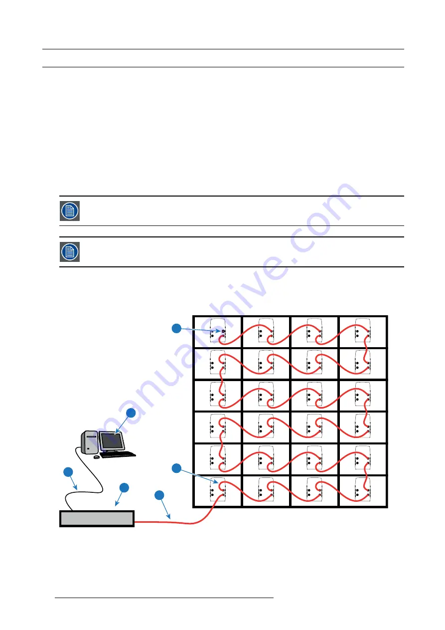
Example of data cabling
The example below shows the data cabling, seen from the rear of the X8 display of four frames wide and six frames high. The data
path is realized in a horizontal direction and starts in the lower left corner (seen from the rear). The settings in the control software
refer to the display seen from the front. So, the
fi
rst tile in the data path has to be indicated as the lower right tile of the display.
POWER
DA
TA
OUT
IN
OUT
IN
POWER
DA
TA
OUT
IN
OUT
IN
POWER
DA
TA
OUT
IN
OUT
IN
POWER
DA
TA
OUT
IN
OUT
IN
POWER
DA
TA
OUT
IN
OUT
IN
POWER
DA
TA
OUT
IN
OUT
IN
POWER
DA
TA
OUT
IN
OUT
IN
POWER
DA
TA
OUT
IN
OUT
IN
POWER
DA
TA
OUT
IN
OUT
IN
POWER
DA
TA
OUT
IN
OUT
IN
POWER
DA
TA
OUT
IN
OUT
IN
POWER
DA
TA
OUT
IN
OUT
IN
POWER
DA
TA
OUT
IN
OUT
IN
POWER
DA
TA
OUT
IN
OUT
IN
POWER
DA
TA
OUT
IN
OUT
IN
POWER
DA
TA
OUT
IN
OUT
IN
POWER
DA
TA
OUT
IN
OUT
IN
POWER
DA
TA
OUT
IN
OUT
IN
POWER
DA
TA
OUT
IN
OUT
IN
POWER
DA
TA
OUT
IN
OUT
IN
POWER
DA
TA
OUT
IN
OUT
IN
POWER
DA
TA
OUT
IN
OUT
IN
POWER
DA
TA
OUT
IN
OUT
IN
POWER
DA
TA
OUT
IN
OUT
IN
LED
WALL
OUT
RS232 IN
DIGITIZER
1
6
5
3
2
4
Image 8-2
1
Local PC with control software.
2
Ethernet connection cable between PC and digitizer.
3
Digitizer.
4
Data cable between digitizer and
fi
rst tile (maximum 5 meter).
5
Data linking cable between tiles.
6
Dummy data plug.
56
R5905160 X8 RENTAL DISPLAY 25/02/2013
Содержание X8
Страница 1: ...X8 Rental Display Installation manual R5905160 03 25 02 2013 ...
Страница 14: ...1 Safety 10 R5905160 X8 RENTAL DISPLAY 25 02 2013 ...
Страница 42: ...6 Setup process of a X8 rental display 38 R5905160 X8 RENTAL DISPLAY 25 02 2013 ...
Страница 56: ...7 Basic setup procedures 52 R5905160 X8 RENTAL DISPLAY 25 02 2013 ...
Страница 62: ...8 Cabling of the X8 display 58 R5905160 X8 RENTAL DISPLAY 25 02 2013 ...
Страница 63: ...9 Maintenance 9 MAINTENANCE Overview Cleaning the X8 display R5905160 X8 RENTAL DISPLAY 25 02 2013 59 ...
Страница 82: ...A Dimensions 78 R5905160 X8 RENTAL DISPLAY 25 02 2013 ...
Страница 86: ...B Specifications 82 R5905160 X8 RENTAL DISPLAY 25 02 2013 ...
Страница 87: ...C Order info C ORDER INFO Overview Spare part order info R5905160 X8 RENTAL DISPLAY 25 02 2013 83 ...
Страница 94: ...D Product Green Compliance 90 R5905160 X8 RENTAL DISPLAY 25 02 2013 ...


