background image

Manual # 26-0208100-00 / Revision E 

ScreenSHAPER – Video Mapping System  13 


Input Active Window

Vertical Blanking Region (back porch)

Vertical Blanking Region (front porch)

H

o

ri

z

o

n

ta

B

la

n

k

in

g

 R

e

g

io

n

 (

b

a

c

k

 p

o

rc

h

)

H

o

ri

z

o

n

ta

B

la

n

k

in

g

 R

e

g

io

n

 (

fr

o

n

p

o

rc

h

)

H Pos

V P

o

s

Capture Area

(Area of Interest)

H Start

H Size

V St

a

rt

V S

ize

VSync Region

H

S

yn

c R

e

g

io

n


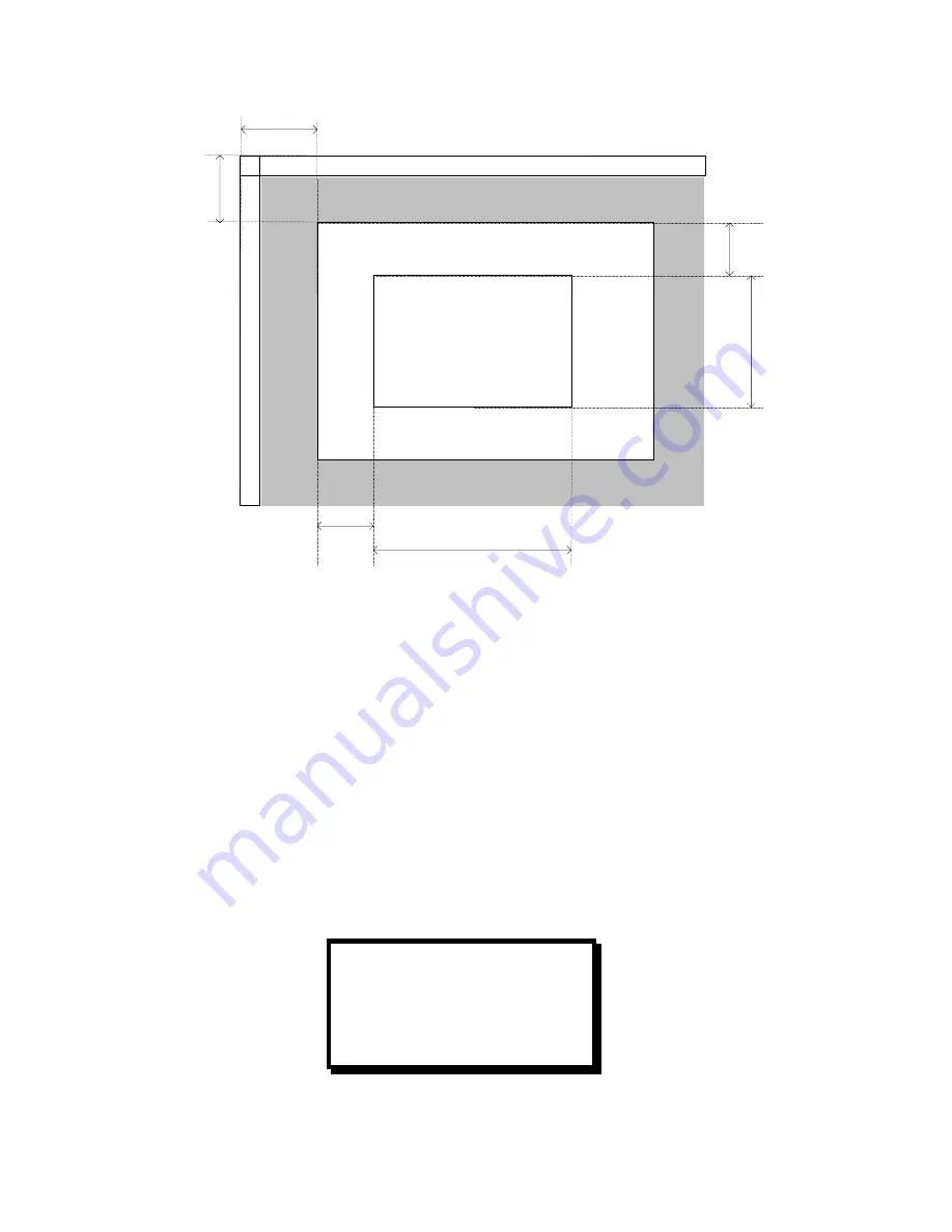
Figure 3-2 Capture Area Definition 


H Position 

This control adjusts the horizontal start of the active video in number of pixels.  The default setting is the position of 
the expected first pixel of the active video, based on the input resolution.  See Figure 3-2 for detail. 

V Position 

This control adjusts the vertical start of the active video in number of lines.  The default setting is the position of the 
expected first line of the active video, based on the input resolution.  See Figure 3-2 for detail. 

Capture Area Submenu 

The following four configuration controls, available when operating in the Rotation Mode, are used to set an input 
“area of interest”.  The default settings define a full-screen based on the resolution of the selected input source.  
These settings can be changed to define a particular rectangle within the full screen to zoom into.  


CAPTURE AREA 
 H START           0 
 H SIZE         1280
 V START           0 
 V SIZE         1024     

Содержание ScreenShaper VMS-100

Страница 1: ...TION AND OPERATOR S MANUAL Manual 26 0208100 00 Revision E INSTALLATION AND OPERATOR S MANUAL Model VMS 100 Barco Folsom LLC 11101 Trade Center Drive Rancho Cordova CA 95670 Phone 916 859 2500 Fax 916 859 2515 ...

Страница 2: ...3 1059 Addition of the storage for Keystone and User defined warp maps April Luong C 07 03 2003 1066 Addition of the Rotation Mode April Luong D 10 10 2003 1155 Modify the Capture and Display Menu interface April Luong E 8 03 04 1301 Expanded to cover new features in Maincode release 2 04 Jim Rodeo Manual 26 0208100 00 ...

Страница 3: ...r cord that is in good condition Refer cord and connector changes to qualified service personnel Use the Proper Fuse To avoid fire hazard use only the fuse having identical type voltage rating and current rating characteristics Refer fuse replacement to qualified service personnel Do Not Operate in Explosive Atmospheres To avoid explosion do not operate this product in an explosive atmosphere Term...

Страница 4: ......

Страница 5: ...er p n 15 0000002 00 as required c Connect the supplied serial cable to the RS 232 connector on the rear of the ScreenSHAPER d Connect the other end of the supplied serial cable to the RS 232 serial port of the external computer e Power on the external computer When it has finished booting install the setup and calibration software from the CDROM Note that this software is not configured for AUTOR...

Страница 6: ...___________________ 12 H POSITION ___________________________________________________________________________________________ 13 V POSITION ___________________________________________________________________________________________ 13 CAPTURE AREA SUBMENU ________________________________________________________________________________ 13 H Start_____________________________________________________...

Страница 7: ...___________________________________________________________________________________________ 22 Baud Rate ____________________________________________________________________________________________ 22 Data Bits _____________________________________________________________________________________________ 22 Stop Bits __________________________________________________________________________________...

Страница 8: ...AUTHORIZATION RMA _______________________________________________________________ 42 BARCO FOLSOM CONTACT INFORMATION___________________________________________________________________ 42 TECHNICAL SPECIFICATIONS _______________________________________________________________________ 44 ...

Страница 9: ...Manual 26 0208100 00 Revision E ScreenSHAPER Video Mapping System 1 1 CHAPTER ONE Introduction What you will find in this chapter About The ScreenSHAPER Typical Operation Features Model VMS 100 ...

Страница 10: ...lays flight simulators keystone correction and home theater Features Accepts RGB and DVI video input with resolutions up to 1280x1024 non interlaced Automatically locks to the input video and processes it in real time Processes the entire input image or a user defined area of interest Supports independent X Y scaling for aspect ratio corrections User selectable output formats VGA 640x480 SVGA 800x...

Страница 11: ...HAPER Video Mapping System 3 2 CHAPTER TWO Installation What you will find in this chapter Rear Panel Connectors Rack Mount Installation Remote Control Connection Video Input Output Connections Power Cord Line Voltage Selection Model VMS 100 ...

Страница 12: ...l Connection The RS 232 serial port is used to connect the ScreenSHAPER to an external computer to support setup and calibration of the ScreenSHAPER The serial port is configured as a DCE device which allows a straight through serial cable to be used to connect the ScreenSHAPER to the PC The cable connecting to the ScreenSHAPER should have a DB 9 male connector Pinouts for the remote port are show...

Страница 13: ...V Power 3 T M D S Data2 4 Shield 15 ground for 5V 4 T M D S Data4 16 Hot Plug Detect 5 T M D S Data4 17 T M D S Data0 6 DDC Clock 18 T M D S Data0 7 DDC Data 19 T M D S Data0 5 Shield 8 Analog Vertical Sync 20 T M D S Data5 9 T M D S Data1 21 T M D S Data5 10 T M D S Data1 22 T M D S Clock Shield 11 T M D S Data1 3 Shield 23 T M D S Clock 12 T M D S Data3 24 T M D S Clock MicroCross Pins Pin Funct...

Страница 14: ...ction When the ScreenSHAPER is used with 230 volt supplies a UL listed line cord rated for 250 volts at 15 amps must be used This cord will be fitted with a tandem prong type plug Tandem Plug La choix de la ligne de voltage se realize automatiquement par Ie ScreenSHAPER Transformateur Graphique On n apas besoin du controller usager pour la choix de la ligne de voltage Das ScreenSHAPER Gerät mu bei...

Страница 15: ...erhalb eines gleichwinkeligen Dreiecks dient dazu den Benutzer auf wichtige Bedienungs und Wartungsanweisungen in der Dem Great beiliegenden Literatur aufmerksam zu machen The rear panel ON OFF switch does not disconnect the unit from input AC power To facilitate disconnection of AC power the power cord must be connected to an accessible outlet near the unit Building Branch Circuit Protection For ...

Страница 16: ......

Страница 17: ...APER Video Mapping System 9 3 CHAPTER THREE Operation What you will find in this chapter Front Panel Controls System Status Display Menu Control Input Video Setup Menu Output Video Setup Menu Test Pattern Menu System Setup Menu Model VMS 100 ...

Страница 18: ...HAPER Front Panel The Front Panel controls include a vacuum fluorescent display VFD an adjustment knob and six illuminated push buttons The operation of each menu displayed on the VFD is described in detail in the following sections of this document Power Up Initialization Locate the power switch on the rear panel and turn the ScreenSHAPER ON While the system is initializing the following message ...

Страница 19: ...rameters are entered they are stored in non volatile memory for future use using the system save menu item Pressing one of the four hot keys will call up the corresponding menu on the VFD The user can scroll through the menu items by turning the ADJUST control knob A pointer at the left of a menu item indicates the current position of the scroll bar When the desired menu item is reached the user p...

Страница 20: ...her on inputs that have a bright border around the entire image This operation may take a minute or so Do not perform an Auto Config on an entirely black image Sync Select The sync format specifies the type of frame sync to be applied to the input video The following settings are available AUTO Automatically determine the output sync format H V Horizontal and Vertical Sync COMP Composite Sync SOG ...

Страница 21: ...first pixel of the active video based on the input resolution See Figure 3 2 for detail V Position This control adjusts the vertical start of the active video in number of lines The default setting is the position of the expected first line of the active video based on the input resolution See Figure 3 2 for detail Capture Area Submenu The following four configuration controls available when opera...

Страница 22: ...t the vertical start of the capture area in number of lines See Figure 3 2 for detail The default setting is 0 V Size V Size is used to set the vertical size of the capture area in number of lines See Figure 3 2 for detail The default setting and the maximum setting is the number of active lines in the input video based on the input resolution Phase Offset Phase Offset is used to adjust the input ...

Страница 23: ... performed This menu allows the operator to balance the colors on the RGB input source Independent Contrast and Brightness adjustments are provided for each color channel The adjustment range for Brightness and Contrast is 25 0 to 25 0 with 0 0 as the default value The Reset Color menu item resets all the fields in this sub menu to the default value 0 0 To reset the color balance controls scroll t...

Страница 24: ...s to SXGA output SVGA XGA and SXGA inputs to XGA output SVGA and XGA inputs to SVGA output Warp Map Index If the warping function is set to ON the image is processed according to the warp map indexed by this parameter There are 9 warp maps that can be loaded and recalled by setting the Warp Map Index The warp map has to be loaded prior to turning the warping function ON It is required that the loa...

Страница 25: ...eeze the display image Format The format is the desired resolution of the output video The following settings are available VGA 640 x 480 SVGA 800 x 600 XGA 1024 x 768 SXGA 1280 x 1024 1280x720 1280x768 1280x960 VGA output is not supported if the input format is 1280x1024 The default setting is SXGA Frame Rate The frame rate specifies the number of times per second that the image is updated The fo...

Страница 26: ... left edge by changing the width of the blank area on the left See Figure 3 3 for detail The default setting is 0 Right Edge Right Edge is used to set the output display area This control adjusts the position of the right edge See Figure 3 3 for detail The default setting is 1280 Top Edge Top Edge is used to set the output display area This control adjusts the top edge by changing the width of the...

Страница 27: ...g is 1 0 which is no correction at all B Gamma The Blue Gamma value is applied to the blue component of the output The default setting is 1 0 which is no correction at all Timing Lock Timing Lock is used to lock the output timing to the input timing It is important to select the output resolution and frame rate that matches the input resolution and frame rate The default setting is DIS Raster Box ...

Страница 28: ...ars GREEN H BAR Green horizontal bars BLUE H BAR Blue horizontal bars YELLOW H BAR Yellow horizontal bars CYAN H BAR Cyan horizontal bars MAGENTA H BAR Cyan horizontal bars BLACK Display a black image GRAY 25 Displays a 25 white image GRAY 50 Displays a 50 white image GRAY 75 Displays a 75 white image WHITE Displays a 100 white image H RAMP Displays a horizontal ramp The default pattern setting is...

Страница 29: ...e left edge feathering equation The default is set to 1 0 Right Feather Left Edge Feathering can be Enable Disable by this control The default is set to Disable Right Width The width of the left feathering area is a value between 0 and half the horizontal width of the input The default is set to 64 Right Gamma The gamma value applied to the left edge feathering equation The default is set to 1 0 C...

Страница 30: ...menu The ScreenSHAPER has one serial port that is configured for RS 232 operation The serial port parameters are under this submenu Configuration parameters entered in this menu are saved in non volatile memory if you issue a SAVE SETTINGS command under the System Setup Menu Echo The user can turn ECHO ON or OFF When ECHO is ON commands received by the unit will be transmitted back to the source d...

Страница 31: ...s Menu The Firmware Versions Menu displays the revision information for the system firmware A sample revision display is shown below Tech Support Menu The Tech Support Menu displays the current firmware version number the customer service telephone number to contact for technical assistance and the Internet address to obtain product news and to download firmware revisions Diagnostics Menu Selectin...

Страница 32: ...ess The VFD Brightness menu selection controls the intensity of the front panel vacuum fluorescent display VFD The adjustment range is 0 to 15 0 is the dimmest setting and 15 is the brightest We recommend using a low intensity setting to avoid burn in of the display The default setting is 8 Operation Mode This control selects the mode of operation Under the Warp Mode the ScreenSHAPER unit can proc...

Страница 33: ...Manual 26 0208100 00 Revision E ScreenSHAPER Video Mapping System 25 4 CHAPTER FOUR Remote Commands What you will find in this chapter ScreenSHAPER Command List Description Model VMS 100 ...

Страница 34: ... EFTA s en w exp Advanced Edge Feather Lut side enable width exponent s L R en 0 1 w 0 640 exp 1 0 5 0 FLIP n Flip Image n 0 2 No Flip H Flip V Flip FREEZ Freez Image n 0 1 DISABLE ENABLE FSB n Force Scaler Black n 0 1 OFF ON GAM n n n Gamma Value command n 1 3 VPC GPC DPC n 0 3 All Red Green Blue n 0 0 5 0 HELP I Help Command i A Z Help Index IBRT op nnn Input Brightness op C R G B I D C n 75 125...

Страница 35: ... 0 1 2 3 50Hz 60Hz 75Hz 59 94Hz OP n Operation Mode n 0 1 WARP ROTATE ORAS n Output Raster Box n 0 1 Disable Enable OSYNC n Output Sync n 0 5 SOG C H V H V H V H V PAR n Parity Type n 0 1 2 NONE ODD EVEN RESET op Reset Factory Defaults op A All ROT n Rotate Image n 0 90 180 270 SAVE Save System Settings SBIT n Stop Bit n 1 2 SYNC n Select Output Sync Mode n 0 1 2 Freerun Linelock Framelock TLCK n ...

Страница 36: ...image intensity regardless of the image intensity n Non blended region threshold Intensity 0 255 n Non blended region offset Intensity 0 255 Query BLKLVL Returns the parameters that defines the black level adjustment n n n Example BLKLVL 2 128 10 Add 10 to the non blended region if the intensity is less then 128 BLKLVL 1 128 190 Set the intensity of the non blended region to 190 if the intensity i...

Страница 37: ...and DBIT n Description Set the number of data bits for serial command port Parameters n 7 8 Query DBIT Returns the number of data bits n Example DBIT 8 Set 8 data bits Command DEBUG password Description Enter or exit the Debug Mode Parameters password Enter the debug mode 0 to exit the debug mode Query DEBUG Returns the current debug mode n Example DEBUG 0 Exit debug mode Command DISP n n n n Desc...

Страница 38: ...thering to 64 pixels on the left side of the image with a gamma of 1 0 Command FLIP n Description Flip the Display Image This command is only recognized in the ROTATE Operation Mode Parameters n flip mode 0 1 2 No Flip Horizontal Flip Vertical Flip Example FLIP 1 Flip the display image left to right FLIP 2 Flip the display image top to bottom Command FREEZ n Description Freeze Display Image Parame...

Страница 39: ...tion Adjusts the Input Brightness value of the current source Parameters op Select Brightness Control C R G B Common Red Green Blue nnn n Brightness value C Range 75 to 125 RGB Range 25 to 25 Query IBRT Returns the Input Brightness of the Common Red Green and Blue of the current source in the format ccc c rr r gg g bb b Example IBRT C 110 Adjusts the Input Brightness for the current source to be 1...

Страница 40: ...g mode for adjusting input clocks per line In the debug mode I Increment D Decrement Exit debug mode Command ICREC n n Description Recall an input configuration Parameters n Configuration index 0 6 for standard library Configuration index 1 for user library n Library User Standard Standard 640x480 800x600 1024x768 1280x1024 1280x720 1280x768 1280x960 Example ICREC 1 0 Loads the user saved input co...

Страница 41: ...ut Sync Mode of the current source in the format n Example ISYNC 0 Sets Scaler to expect SOG on the input channel Command KEY n n Description Load a new keystone warp map from flash into the coefficient dual port ram of the warper chip This command is only recognized in the WARP Operation Mode Parameters n V Index of keystone 0 10 n H Index of keystone 8 8 Query KEY Returns the currently selected ...

Страница 42: ...GA 1280x1024 4 1280x720 5 1280x768 6 1280x960 VGA is not supported if the input format is 1280x1024 Query OCRECF Returns the Output Resolution in the format n Example OCRECF 2 Select output format to be XGA Command OFRATE n Description Adjusts the Output Frame Rate Parameters n frame rate 0 1 2 3 50Hz 60Hz 75Hz 59 94Hz Query OFRATE Returns the Output Frame Rate in the format n Example OFRATE 1 Set...

Страница 43: ...ple OSYNC 3 Adjusts the Output Sync value to be H V Command PAR n Description Set the parity type for serial command port Parameters n 0 1 2 NONE ODD EVEN Query PAR Returns the parity type n Example PAR 1 Set ODD parity Command RESET op Description Resets all system variables or reset the system to factory defaults Parameters op Reset operation A F All Factory Example RESET A Resets all system var...

Страница 44: ...for pixel clock generation Note External sync required if n 2 Parameters n 0 1 2 Freerun Lock to input timing Lock to external sync Query TLCK Returns 0 for free run mode and 1 for lock output to input n Example TLCK 1 Lock output timing to input timing Command TPAT typ bx gr Description Set the test pattern parameters Parameters typ Test pattern type 0 15 Off Burst1 Burst2 Grey H Bars Red H Bars ...

Страница 45: ...KEYSTONE the warp mapused is set by the KEY command This command is only recognized in the WARP Operation Mode Note The keystone function currently only supports these input output settings SVGA XGA and SXGA inputs to SXGA output SVGA XGA and SXGA inputs to XGA output SVGA and XGA inputs to SVGA output Parameters n 0 1 2 OFF ON Keystone Query WARP Returns the warp status n Example WARP 1 Enable th...

Страница 46: ...38 ScreenSHAPER Video Mapping System Manual 26 0208100 00 Revision E 5 CHAPTER FIVE Software Upgrade Instructions What you will find in this chapter Software Upgrade Instructions Model VMS 100 ...

Страница 47: ... 98 NT 2000 XP Flash File Loader ScreenSHAPER Software files The Flash File Loader with the Software files can be downloaded from our FTP site as described below Connecting to Barco Folsom Barco Folsom s FTP site address is ftp folsom com If you are using an FTP client logon to our site using anonymous for the user name and your email address as the password ex johndoe somecompany com However if y...

Страница 48: ... RS232 Config menu and select COM Port 4 In the Communication Settings window select the COM port the ScreenSHAPER port is attached to by clicking on the appropriate COM choice 5 The ScreenSHAPER RS 232 serial port defaults to a baud rate of 38400 baud 38 4K Uploading Files to the ScreenSHAPER Unit 1 Once communications have been established and verified click on the Open script file to read and u...

Страница 49: ...8100 00 Revision E ScreenSHAPER Video Mapping System 41 6 CHAPTER SIX Barco Folsom Information What you will find in this chapter Warranty RMA Information Technical Support General Contact Information Model VMS 100 ...

Страница 50: ...ed to return for repair please call 888 414 7226 and ask for a Sales Engineer to receive a Return Merchandise Authorization number RMA RMA Conditions a Prior to returning any item you must receive a Return Merchandise Authorization RMA number b All RMA numbers must appear on their return shipping label c RMA numbers are valid for ten 10 days from issue date d All shipping and insurance charges on ...

Страница 51: ...Manual 26 0208100 00 Revision E ScreenSHAPER Video Mapping System 43 A APPENDIX A Technical Specifications Model VMS 100 ...

Страница 52: ...mber 1 Format RS 232 Baud Rate 1200 9600 19 2K and 38 4K Parity None Even and Odd Data Bits 7 or 8 Stop Bits 1 or 2 Echo On or Off Hardware Handshake On or Off Connector DB 9F Physical Height 1RU 1 75 44 5 mm Width 17 43 2 cm or 19 48 3 cm with rack mount option Depth 16 45 5 cm Weight 9 lbs 4 1 kg Shipping Weight 13 lbs 5 91 kg Input Power 98 264 VAC 47 63 Hz 45 W max Environmental Temperature 0 ...

Отзывы: