Barco R9001290 Скачать руководство пользователя страница 7

Safety Instructions

1-1

5975338 BARCOVISION 9200 210497

1

SAFETY INSTRUCTIONS

Projectors are built in accordance with the requirements of the
international safety standards IEC950, UL 1950 and CSA C22.2 No.
950, which are the safety standards of information technology equip-
ment including electrical business equipment.

These safety standards impose important requirements on the use of
safety critical components, materials and isolation, in order to protect
the user or operator against the risk of electric shock and energy
hazard, and having access to live parts.
Safety standards also impose to the internal and external temperature
rises, radiation levels, mechanical stability and strength, enclosure
construction and protection against risk of fire.

Simulated single fault condition testing ensures the safety of the
equipment to the user even when the equipment's normal operation
fails.

Installation instructions

Before operating your projector please read this manual thoroughly,
and retain it for future reference.

Installation and preliminary adjustments should be performed by
qualified BARCO personnel or authorized BARCO service dealers.

OWNER’S RECORD

The part number and serial number are located at the front of the
projector. Record these numbers in the spaces provided below. Refer
to them whenever you call upon your BARCO dealer regarding this
product.

PART NUMBER:

SER. NUMBER:

DEALER:

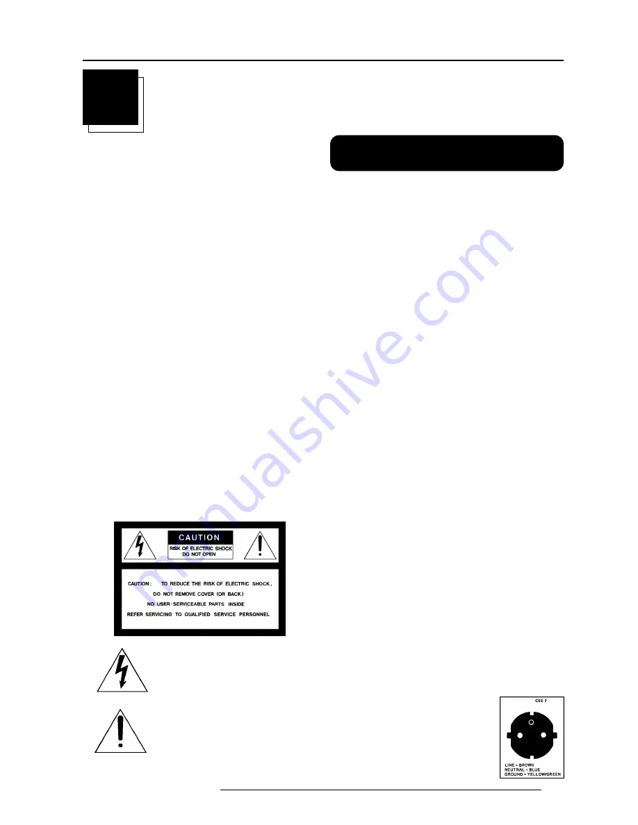
The lightning flash with an arrowhead within a
triangle is intended to tell the user that parts
inside this product are risk of electrical shock
to persons.

The exclamation point within a triangle is
intended to tell the user that important operat-
ing and/or servicing instructions are included
in the technical documentation for this equip-
ment.

Warning

To prevent fire or electrical shock hazard, do not expose this

projector to rain or moisture

Federal communication commission (FCC statement)

This equipment has been tested and found to comply with the limits
for a class A digital device, pursuant to Part 15 of the FCC Rules.
These limits are designed to provide reasonable protection against
harmful interference when the equipment is operated in a commercial
environment.  This equipment generates, uses, and can radiate radio
frequency energy and, if not installed and used in accordance with the
instruction manual, may cause harmful interference to radio commu-
nications.  Operation of this equipment in a residential area is likely
to cause harmful interference in which case the user will be required
to correct the interference at his own expense.

Instructions to the user :

if this equipment does cause interference to radio or television
reception, the user may try to correct the interference by one or more
of the following measures :

- Re-orientation of the receiving antenna for the radio or television.
- Relocate the equipment with respect to the receiver.
- Plug the equipment into a different outlet so that the equipment and

receiver are on different branch circuits.

• Fasten cables connectors to the equipment by mounting screws.

Note :
The use of shielded cables is required to comply within the limits of
Part15 of FCC rules and EN55022.

General safety instructions.

* All the safety and operating instructions should be read before using

this unit.

* The operating instructions manual should be retained for future

reference.

* All warnings on the projector and in the documentation manuals

should be adhered to.

* All instructions for operating and use of this equipment must be

followed precisely.

ON  SAFETY

* This product should be operated from an AC power source. This

projector may be connected to an IT-power system.

* This product is equipped with a 3-wire grounding plug, a plug having

a third (grounding) pin. This plug will only fit into a grounding-type
power outlet. This is a safety feature. If you are unable to insert the
plug into the outlet, contact your electrician to replace your
obsolete outlet. Do not defeat the purpose of the grounding-type
plug.

WARNING FOR THE CUSTOMERS: THIS APPARATUS MUST BE
GROUNDED  (EARTHED)  via the supplied 3 conductor AC power
cable.
(If the supplied power cable is not the correct one, consult your
dealer.)

Mains lead (AC Power cord) with CEE 7 plug:
The colors of the mains lead are colored in
accordance with the following code:

Green-and-yellow:

Earth (safety earth)

Blue:

Neutral

Brown:

Line

Содержание R9001290

Страница 1: ...R9001290 OWNER S MANUAL VISION 9200...

Страница 2: ......

Страница 3: ...BARCO PROJECTION SYSTEMS Date 280497 Art No R5975338 R9001290 OWNER S MANUAL VISION 9200 Rev 01...

Страница 4: ...manual is subject to change without notice Produced by BARCO NV April 1997 All rights reserved Trademarks are the rights of their respective owners Printed in Belgium BARCO nv Projection Systems Noor...

Страница 5: ...t module insertion into the projector 6 2 Video S video input module 6 3 RGB analog input module 6 4 Component input module 6 5 RGB3S RG3sB input module 6 6 Connecting a computer e g IBM PC or compati...

Страница 6: ...SERVICE MODE 10 1 How to activate the password function 10 1 Start up the Service mode 10 1 Convergence adjustment of the LCD panels 10 2 Modify password 10 5 Lamp run time history 10 5 Reset lamp run...

Страница 7: ...e reasonable protection against harmful interference when the equipment is operated in a commercial environment This equipment generates uses and can radiate radio frequency energy and if not installe...

Страница 8: ...interf rences Le cas ch ant l utilisateur devra prendre toutes les mesures requises pour les amoindrir ses propres frais Instructions pour l utilisateur Si cet quipement cause des interf rences de ra...

Страница 9: ...ot operate normally when the operating instructions are followed Adjust only those controls that are covered by the operating in structions since improper adjustment of the other controls may result i...

Страница 10: ...au Si l appareil ne fonctionne pas normalement bien que les instruc tions soient correctement suivies Ne r gler que les commandes d crites dans les instructions de fonctionnement car un mauvais r glag...

Страница 11: ...these bolts because these bolts must be used to mount the feet to the projector Mount first the metal parts with the removed bolts and turn in then both plastic parts to finish the feed Warning To pre...

Страница 12: ...andle a little to the bottom of the RCU Lift up the top side of the cover at the same time fig 1 Insert the new 9 V battery type E block or equivalent in the lower compartment and connect the battery...

Страница 13: ...darkest and lightest parts of the image With bigger screens the wash out becomes more important As a general rule darken the room to the point where there is just sufficient light to read or write co...

Страница 14: ...e order number is given in the tabel in the same appendix B Start the installation procedure for the projector as described in the manual Inputs and computer video format input compatibility Some exam...

Страница 15: ...ansmitted from the RCU Power switch 1 on 0 off Power input autoranging from 200 to 240 Vac Identification plate name serial number art number Voltage identification plate name serial number art number...

Страница 16: ...switch is switched on to switch off the projector without switching off the power switch PAUSE to stop projection for a short time press PAUSE The image disappears but full power is retained for immed...

Страница 17: ...ront Table Front Ceiling Rear Table Rear Ceiling When switching on and the projector displays an image as illustrated below an adaptation of the projector configuration is required The projector s con...

Страница 18: ...y Color ENTER displays the Installation menu EXIT returns to the Main menu A marker indicates the actual configuration Push the control disk up or down to select the corresponding configuration with r...

Страница 19: ...STANDBY ENTER TEXT EXIT PAUSE 2 1 4 3 5 6 8 0 9 7 Stand by button ADJ EXIT STBY TEXT BRIGHTNESS SHARPNESS TINT COLOR CONTRAST FREEZ 0 9 7 8 6 5 4 3 2 1 ENTER PAUSE PHASE HELP Switching on Use the pow...

Страница 20: ...ot 2 RGB analog input module Slot 3 Component input module Input module insertion into the projector Power down the projector and disconnect the power cord from the wall outlet Remove the dummy plate...

Страница 21: ...operational mode Use the control disk to select Input Slots by pushing it up or down and press ENTER The internal system will scan the inputs and displays the result in the Input Slots menu Push the...

Страница 22: ...RGB input selection Key in the corresponding slot number on the RCU or the local keypad Straps on module level Floating or non floating input Red J3 strap yes non floating strap no floating Green J4 s...

Страница 23: ...ideo 4 x BNC R Y 0 7 Vpp 3 dB B Y 0 7 Vpp 3 dB Y 0 7 Vpp 3 dB 1 Vpp 3 dB if Tri level sync on green Composite sync 1 Vpp to 4 Vpp 3 dB All input signals are always 75 ohm terminated even if the module...

Страница 24: ...RGB3S RG3sB input module Connect your RGB signals with Tri level sync e g a professional VCR to the RGB 3 level sync input module RGB3S RG3sB analog 5 x BNC Red 0 7 Vpp 3 dB Blue 0 7 Vpp 3 dB Green 0...

Страница 25: ...connection allow storage of multiple projector configurations and set ups wide range of control possibilities address range from 0 to 255 b VISION communications sending VISION to the projector or cop...

Страница 26: ...75 ON ON ON Connecting a RCVDS 05 to the projector Up to 10 inputs 20 when video inputs with the RCVDS 05 and 90 inputs when RCVDS s are linked via the expansion module Serial communication with the...

Страница 27: ...ay cau se u nde si re d o per ati o n c Point the front of the RCU directly at one of the IR sensors of the projector When using the wireless remote control make sure you are within the effective ope...

Страница 28: ...d in a Text box This text box disappears after a few seconds To continue using the RCU it is necessary to enter the same address with the digit buttons address between 0 and 9 For example if the Addre...

Страница 29: ...ght System Settings by pushing the control disk key up or down and press ENTER to select this option The System Settings menu will be displayed on the screen MAIN MENU 832b Picture Control Audio Contr...

Страница 30: ...d rate of the projector must be the same as the baud rate of the connected computer When there is a difference consult Set up of the baud rate for communication with a computer in chapter Connections...

Страница 31: ...i interlaced blanc not interlaced xxxXxxx active pixel rating Sx source number xxx file extension first character is C for custom made files or S for standard files The second and third character is u...

Страница 32: ...ll be displayed in the upper right corner EDIT FILE 851 pal c50 Horizontal Total 864 pixels Active 675 pixels Shift 114 pixels Period 63 7 s Vertical field Total 312 lines Active 278 lines Shift 21 li...

Страница 33: ...image height is displayed no missing lines Vertical shift shift the image up and down push control disk up or down on the screen until the correct image position is obtained Interlaced On or Off this...

Страница 34: ...tten in the FROM area and the TO area The TO area is active Press ENTER to select the separate characters Push the control disk to the right or to the left to select the desired character Change that...

Страница 35: ...a selected file out of the list of files Use the control disk to select DELETE and press ENTER The delete menu will be displayed FILE SERVICE 847g Load Edit Rename Copy Move Delete Options DELETE FILE...

Страница 36: ...Source Set Up 8 6 5975338 BARCOVISION 9200 210497...

Страница 37: ...k up or down to select Signal Operations The default setting for all items are shown in the menu next to this text To change a value in the Signal Operation menu select first the item by pushing the j...

Страница 38: ...down and press ENTER to toggle between Slow and Fast Note Sync is normally used in the SLOW position The FAST position is used to compensate for unsteady sync pulses from older video playback equipme...

Страница 39: ...nd press ENTER to select All functions e g move enlarge reduce stretch can be done on a Window or on a Picture SCREEN OPERATIONS 868a Zoom Pan Geometry off Configure 870 Screen Window Picture Window A...

Страница 40: ...rds 870 870 window stretchesthewindowinthe horizontal direction 870 870 window Compresses the window in the horizontal direction 870 870 window stretches the window in the vertical direction 870 870 w...

Страница 41: ...imensions Picture The picture can be moved enlarged reduced within a created window picture Displays the covered info on the left side you have to consider that you are moving your camera to the left...

Страница 42: ...orizontal direction Stretches the picture in the vertical direction Compressesthepictureinthe vertical direction Zooms in the picture both horizontal and vertical di rections simultanious Zooms out th...

Страница 43: ...is displayed on the screen Parts of the image cannot be displayed and will be lost When conversion is off the geometry function is disabled Geometry The Geometry function can only be activated when co...

Страница 44: ...of the projected image in horizontal way Reduce the upper part of the projected image in horizon tal way Enlarge the lower part of the projected image in horizontal way Reduce the lower part of the pr...

Страница 45: ...over see Set up of the baud rate for communication with a computer chapter Connections When DIP switch 4 S2 is in the ON position password is activated OFF position password not activated service mode...

Страница 46: ...ure to adjust the LCD panels Open the top cover as described in Gaining access to the DIP switches under Connecting to a computer in chapter Connections The three mounting parts for the LCD s two are...

Страница 47: ...hese lines must be converged with the green lines The drawn screws and numbers are displayed in red Follow next steps a Adjust first screws 4 5 and 6 to obtain an optimal focus for respec tive lines 4...

Страница 48: ...e mentioned steps for the respective lines If all lines are correctly converged press EXIT to return to the Test pattern menu Blue on green convergence Use the control disk to highlight Blue on green...

Страница 49: ...rns to the Service menu When the password is not correct an error message Invalid pass word will be displayed Press EXIT to continue The projector returns to the Service menu without changing the pass...

Страница 50: ...rning will be displayed Risk of electrical shock Reset lamp run time is reserved to qualified service personnel If you are not qualified press EXIT to cancel the reset operation WARNING RISK OF ELECTR...

Страница 51: ...0 087 31 469 28 322 900 720 449 400 COMPUSC4 1024 X 480I 29 945 30 694 39 779 1296 1024 512 480 VGA_72V 640 X 480 72 800 37 856 31 496 832 640 520 480 VGA_GR 640 X 480 59 941 31 469 25 175 800 640 525...

Страница 52: ...Standard Source Set Up Files A 2 5975388 BARCOVISION 9200 210497...

Страница 53: ...rol by pushing the indicated handle a little to the bottom of the RCU Lift up the top side of the cover at the same time fig 1 Remove the battery from the compartment and disconnect the contact plate...

Страница 54: ...ure for the other HD lens To minimize the possibility of damaging the optical coating or scratch ing exposed lens surfaces we have developed recommendations for cleaning lenses FIRST we recommend you...

Страница 55: ...distance HD 1 2 1 Metric PD 1 264 x SW 0 126 0 018 SW Inch PD 1 264 x SW 4 961 27 90 SW HD 2 2 1 Metric PD 2 0566 x SW 0 16 0 029 SW Inch PD 2 0566 x SW 6 299 44 95 SW HD 3 3 1 Metric PD 3 33 x SW 0...

Страница 56: ...shown in the diagram below source input 1 source number 1 source number 91 file A file A source input 2 source number 2 source number 92 file B file B source input 3 source number 3 source number 93 f...

Страница 57: ...5975338 BARCOVISION 9200 210497 P RCU INPUT SOURCES 1 PROJECTOR RCVDS 2 3 4 5 6 1 2 3 5 6 7 8 9 10 INPUT SOURCES 7 P RCU INPUT SOURCES 1 PROJECTOR RCVDS 2 3 4 5 6 1 2 3 5 6 7 8 9 10 INPUT SOURCES 7 I...

Отзывы: