29. Convergence adjustment
Necessary tools
•
2x R847204 : steel screwdriver with 1/16” ended hex blade.
•
R847205 : square drive socket with soldered hexagon key of 2.5 mm
•
R847203 : Steel screwdriver with 0.05” ended hex blade
•
Allen key 3 mm
•
Allen key 2.5 mm
How to re-converge
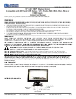
1. Remove first the convergence cover plate (A) in the top plate by turning out the necessary screws.
A
Image 29-4
Convergence cover
2. Is your projector an FLM HD projector?
If yes, Loosen the 4 screws Cr and the 4 screws Cg on the heat pipes of HD light processors. Then continue with step 3.
Cg
Cr
Image 29-5
Heat pipes on HD light processor
If no, go to step 3
3. Put the square drive socket, with a soldered hexagon key onto a ratchet.
4. Carefully release the 4 lock-down screws, holding the DMD unit onto Prism frame.
Tip:
Release the lock-down screws in a way the DMD assembly becomes just movable. Keep in mind that at the end of the
re-convergence, tightening the DMD unit can cause some small convergence drift.
5. Start the re-convergence in the center of the image as follows (using tool R847204):
- Adjust the control Gb1 until the crossing of the center Green convergence pattern coincide with the Top left/Bottom right
diagonal line of the center Blue convergence pattern.
- Adjust the control Gb2 & Gb3 simultaneously until the crossing of the center Green convergence pattern coincide with the Top
right/Bottom left diagonal line of the center Blue convergence pattern.
316
R59770072 FLM SERIES 19/03/2007
Содержание FLM series
Страница 1: ...FLM series Service manual R59770072 00 19 03 2007...
Страница 6: ...Table of contents 4 R59770072 FLM SERIES 19 03 2007...
Страница 10: ...1 Safety 8 R59770072 FLM SERIES 19 03 2007...
Страница 11: ...2 General info 2 GENERAL INFO Overview Location of modules Spare part kits R59770072 FLM SERIES 19 03 2007 9...
Страница 86: ...6 Removal and installation of projector covers 84 R59770072 FLM SERIES 19 03 2007...
Страница 96: ...8 Lamp and lamp house 94 R59770072 FLM SERIES 19 03 2007...
Страница 102: ...9 Input communication unit 100 R59770072 FLM SERIES 19 03 2007...
Страница 125: ...13 Cold mirror assembly Image 13 5 Remove of cold mirror R59770072 FLM SERIES 19 03 2007 123...
Страница 130: ...13 Cold mirror assembly 8 Reinstall the side cover 128 R59770072 FLM SERIES 19 03 2007...
Страница 133: ...14 Lens holder F Image 14 4 R59770072 FLM SERIES 19 03 2007 131...
Страница 136: ...14 Lens holder Image 14 10 The lens holder has to be adjusted after installation 134 R59770072 FLM SERIES 19 03 2007...
Страница 140: ...14 Lens holder 138 R59770072 FLM SERIES 19 03 2007...
Страница 150: ...15 Vertical and Horizontal shift motors Image 15 13 Remove motor Image 15 14 148 R59770072 FLM SERIES 19 03 2007...
Страница 154: ...15 Vertical and Horizontal shift motors 152 R59770072 FLM SERIES 19 03 2007...
Страница 180: ...16 FLM liquid cooling circuit 178 R59770072 FLM SERIES 19 03 2007...
Страница 190: ...17 Heat exchanger 188 R59770072 FLM SERIES 19 03 2007...
Страница 204: ...18 Cooling pump 202 R59770072 FLM SERIES 19 03 2007...
Страница 208: ...19 Shutter replacement 206 R59770072 FLM SERIES 19 03 2007...
Страница 212: ...20 Formatter Interface Board 210 R59770072 FLM SERIES 19 03 2007...
Страница 217: ...21 Pixel map processor board Image 21 7 PMP removal R59770072 FLM SERIES 19 03 2007 215...
Страница 220: ...21 Pixel map processor board 218 R59770072 FLM SERIES 19 03 2007...
Страница 228: ...22 LCD panel replacement 226 R59770072 FLM SERIES 19 03 2007...
Страница 234: ...23 Keypad board replacement 232 R59770072 FLM SERIES 19 03 2007...
Страница 288: ...25 Peltier replacement 286 R59770072 FLM SERIES 19 03 2007...
Страница 314: ...28 Start pulse generator 312 R59770072 FLM SERIES 19 03 2007...
Страница 326: ...Glossary 324 R59770072 FLM SERIES 19 03 2007...