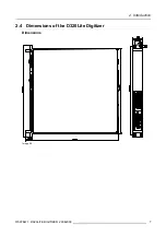
background image

1. Safety

1.2

Important Warnings

Important Warnings:

Risk of electric shock:

Image 1-1
Risk of electrical shock

Risk of electric shock. Do not open. To reduce the risk of electric shock, do not remove cover (or
back). No user-serviceable parts inside. Refer servicing to qualified service personnel.
The lightning flash with an arrowhead within a triangle is intended to tell the user that parts inside this
product may cause a risk of electrical shock to persons.
The exclamation point within a triangle is intended to tell the user that important operating and/or
servicing instructions are included in the technical documentation for this equipment.

Maximum ambient temperature:

The maximum recommended ambient temperature for this equipment is 40 C.

Flammable materials:

Keep flammable materials away from the installation (such as curtains). A lot of energy is transferred
into heat. The installation should be such that the amount of air flow required for safe operation of the
equipment is not compromised. Proper ventilation must be provided.

This equipment MUST be earthed:

In order to protect against risk of electric shock, the installation should be properly grounded. Defeat-
ing the purpose of the grounding type plug will expose you to the risk of electric shock. This apparatus
must be grounded (earthed) via the supplied 3 conductor AC power cord. (If the supplied power cord
is not the correct variant, consult your dealer.)

Power system:

It is recommended to use a TN-S power distribution system (a power distribution system with a sep-
arate neutral and grounding conductor) in order to avoid large ground currents loops due to voltage
differences in the neutral conductor. The total electrical installation should be protected by an appro-
priate rated disconnect switch, circuit breakers and Ground Fault Current Interrupters. The installation
shall be done according to the local electrical installation codes. In Europe special attention should be
given to EN 60364, the standard for electrical installation of buildings. In Germany VDE 0100 should
be adhered to.

Mains cords:

The power cords delivered with this system have special properties for safety. They are not user
serviceable. If the power cords are damaged, replace only with new ones. Never try to repair a power
cord.

2

R5976471 D320LITE DIGITIZER 29042003

Содержание D320LITE

Страница 1: ...EVENTS D320LITE DIGITIZER R9851560 INSTALLATION GUIDELINES 29042003 R5976471 00 ...

Страница 2: ...Barco nv Events Noordlaan 5 B 8520 Kuurne Phone 32 56 36 89 70 Fax 32 56 36 88 24 E mail events barco com Visit us at the web www barco com Printed in Belgium ...

Страница 3: ...ence or part of Barco If the purchaser or a third party carries out modifications or repairs on good delivered by Barco or if the goods are handled incorrectly in particular if the systems are commissioned operated incorrectly or if after the trans fer of risks the goods are subject to influences not agreed upon in the contract all guarantee claims of the purchaser will be rendered invalid Not inc...

Страница 4: ......

Страница 5: ...hen replacement of the defective parts must be undertaken immediately Protect the power data cords from being walked on or pinched particularly at plugs convenience re ceptacles and the point where they exit from the apparatus Replace damaged power data cords immediately Only use attachments accessories specified by the manufacturer Disconnect the power to this apparatus during lightning storms or...

Страница 6: ...UST be earthed In order to protect against risk of electric shock the installation should be properly grounded Defeat ing the purpose of the grounding type plug will expose you to the risk of electric shock This apparatus must be grounded earthed via the supplied 3 conductor AC power cord If the supplied power cord is not the correct variant consult your dealer Power system It is recommended to us...

Страница 7: ...he wall outlet does not exceed 15 amperes Cabinet openings Never push objects of any kind into this product through cabinet slots as they may touch dangerous high voltage points or short out parts that could result in a risk of fire or electrical shock Never spill liquid of any kind on the product Should any liquid or solid object fall into the cabinet unplug the set and have it checked by qualifi...

Страница 8: ...1 Safety 4 R5976471 D320LITE DIGITIZER 29042003 ...

Страница 9: ...hem customize them With analog and digital outputs which allow for the control of displays as well as built in control software the D320Lite gives you control over everything from basic set up to configuration and advanced feature control Image 2 1 System overview 2 2 Order info D320Lite Digitizer Order info Article No Description R9851560 D320Lite Digitizer 2 3 Technical summary Summary Type Valu...

Страница 10: ...ng Intuitive positioning interface Connectors RS 232 RJ 11 Ethernet RJ 45 Effects Anamorphic imaging Chroma keying per input Alpha keying per input Z order control Windowing View ports Ruggedness IP 10 Dimensions D320Lite 486 x 482 x 53 W x D x H Dimensions D320Lite input Units 41 x 181 x 103 W x D x H Weight 7 kg Operating Temperature 0 ºC 45 ºC Power consumption 130 Watt max at 85 264 Volt 50 60...

Страница 11: ...2 Introduction 2 4 Dimensions of the D320Lite Digitizer Dimensions Image 2 2 R5976471 D320LITE DIGITIZER 29042003 7 ...

Страница 12: ...2 Introduction 8 R5976471 D320LITE DIGITIZER 29042003 ...

Страница 13: ...re that air flows freely in vent holes Blocking these holes will greatly reduce the reliability of the unit and lead to the possibility of overheating The D320Lite Digitizer should operate from an AC power source The D320Lite Digitizer is equipped with Power Supply Autoranging from 85 to 264 volt 50 60 Hertz When installed in a rack the mounting should be such that no hazardous condition is achiev...

Страница 14: ... Connections Rear panel inputs outputs Image 3 2 A LED WALL PROJECTOR OUTPUT B Power Switch C Power input D Not used E Retractable dust filter F COM1 RS232 input G Not used H Not used I TCP IP Ethernet LAN connector 10 R5976471 D320LITE DIGITIZER 29042003 ...

Страница 15: ...rate the unit without a good working air filter in place G COM1 RS232 input Direct master RS232 input port for communication links with local PC H Not used I Not used J TCP IP Ethernet LAN connector For future use 3 3 Removing and inserting a D320Lite Digitizer input module There is no need to switch off the D320Lite Digitizer to remove or insert an input module The input modules are hot swappable...

Страница 16: ...3 Physical Installation of the D320Lite Digitizer Maximum two HDSDI input modules may be inserted in one D320Lite Digitizer 12 R5976471 D320LITE DIGITIZER 29042003 ...

Страница 17: ...ource DVI data in 162 MHz pixel clock Resolution from VGA to UXGA 60 Hz DVI compliant DVI loop through Amber LED upper LED on the front side will be lit indicating module start up When placed in an input slot the green LED lower LED on the front side will be lit indicating that the system acknowledges the module Image 4 1 Image 4 2 Order info Article No Description R9850960 D320Lite Digitizer DVI ...

Страница 18: ... film either continuous or intermittent film detection When placed in an input slot the green LED lower LED on the front side will be lit indicating that the system acknowledges the module Image 4 3 Image 4 4 Order info Article No Description R9850970 D320Lite Digitizer SDI input module 4 3 HDSDI input module Maximum two HDSDI input modules may be inserted in one D320Lite Digitizer 14 R5976471 D32...

Страница 19: ...PTE 274M o 1920x1080 29 97 1 1 SMPTE 274M o 1920x1080 25 1 1 SMPTE 274M o 1920x1080 24 1 1 SMPTE 274M o 1920x1080 23 98 1 1 SMPTE 274M Interlaced o 1920x1035 60 2 1 SMPTE 260M o 1920x1035 59 94 2 1 SMPTE 260M o 1920x1080 60 2 1 SMPTE 274M o 1920x1080 59 94 2 1 SMPTE 274M o 1920x1080 50 2 1 SMPTE 274M o 1920 1080 50 2 1 1250 SMPTE 295M o 1920x1080 24 Segmented SMPTE 274M o 1920x1080 23 98 Segmented...

Страница 20: ...em acknowledges the module Image 4 7 Image 4 8 Order info Article No Description R9850920 D320Lite Digitizer CVBS S VID input module 4 5 YUV RG s B input module Technical info Component Video BNC R Y 0 7Vpp 3dB 75 Ohm termination Ys 1Vpp 3dB 0 7V Luma 0 3V Sync 75 Ohm termination B Y 0 7Vpp 3dB 75 Ohm termination RG s B BNC R 0 7Vpp 3dB 75 Ohm termination G s 1Vpp 3dB 0 7Vpp G 0 3Vpp Sync 75 Ohm t...

Страница 21: ...SXGA and UXGA version available Amber LED upper LED on the front side will be lit indicating recognition of film either continuous or intermittent film detection When placed in an input slot the green LED lower LED on the front side will be lit indicating that the system acknowledges the module Image 4 11 Image 4 12 Order info Article No Description R9850950 D320Lite Digitizer RGB analog SXGA inpu...

Страница 22: ... 4 7 Dummy input module Technical info Dimensions 103 x 181 x 41 W x D x H Image 4 13 Image 4 14 Order info Article No Description R9850930 D320Lite Digitizer dummy input module 18 R5976471 D320LITE DIGITIZER 29042003 ...

Страница 23: ... connectors for RS232 connection between local control PC and COM1 RS232 input port of the master Digitizer image 5 5 Z3499209 One meter data cable with MDR connectors Used to make a connection between the LOOP OUT connector of the previous Digitizer and the LOOP IN connector of the next Digitizer image 5 6 R9851210 Five meter data cable with DVI connectors Used to connect the LED WALL OUTPUT with...

Страница 24: ...5 Cables and accessories for the D320Lite Digitizer Image 5 4 Image 5 5 Image 5 6 Image 5 7 Image 5 8 Image 5 9 20 R5976471 D320LITE DIGITIZER 29042003 ...

Страница 25: ... 1 Connect the RS232 communication port of the local control PC with the COM1 RS232 input port of the D320Lite Digitizer 2 Connect the LED WALL OUTPUT from the D320Lite Digitizer with the display 3 Provide the available video sources to the D320Lite input modules 4 Configure the D320Lite Digitizer and the Display with the control software installed on the local control PC R5976471 D320LITE DIGITIZ...

Страница 26: ...6 Configuration Schemes 22 R5976471 D320LITE DIGITIZER 29042003 ...

Страница 27: ...al R5976380 for more information about the XLite Toolset 7 2 Version Control Manager VCM General introduction The Version Control Manager R9850044 is a stand alone program to update the software and firmware of D320Lite Digitizer The software runs from CD ROM and acts like a wizard So no installation is required The software runs on a Windows platform Refer to the manual R5976407 for more informat...

Страница 28: ...7 Control Software 24 R5976471 D320LITE DIGITIZER 29042003 ...

Страница 29: ...he dust from the filter and remove remaining dust with a dry cloth 3 Place the clean dust filter back in the D320Lite Digitizer Image 8 1 8 2 Cleaning the cabinet Do not use liquid cleaners or aerosol cleaners Never use strong solvents such as thin ner or benzine or abrasive cleaners since these will damage the cabinet How to clean the cabinet 1 Unplug the D320Lite Digitizer from the wall outlet b...

Страница 30: ...8 Maintenance of the D320Lite Digitizer 26 R5976471 D320LITE DIGITIZER 29042003 ...

Страница 31: ...9 Options 9 OPTIONS 9 1 Overview Order info Article No Description R9851510 Climate Control Case for using the D320Lite Digitizer outdoor R5976471 D320LITE DIGITIZER 29042003 27 ...

Страница 32: ...9 Options 28 R5976471 D320LITE DIGITIZER 29042003 ...

Страница 33: ...ordlaan 5 B 8520 Kuurne Phone 32 56 36 89 70 Fax 32 56 36 88 24 E mail antoon dejaegher barco com Web www barco com From Date Please correct the following points in this documentation R5976471 00 page wrong correct R5976471 D320LITE DIGITIZER 29042003 ...

Отзывы: