6. Getting started
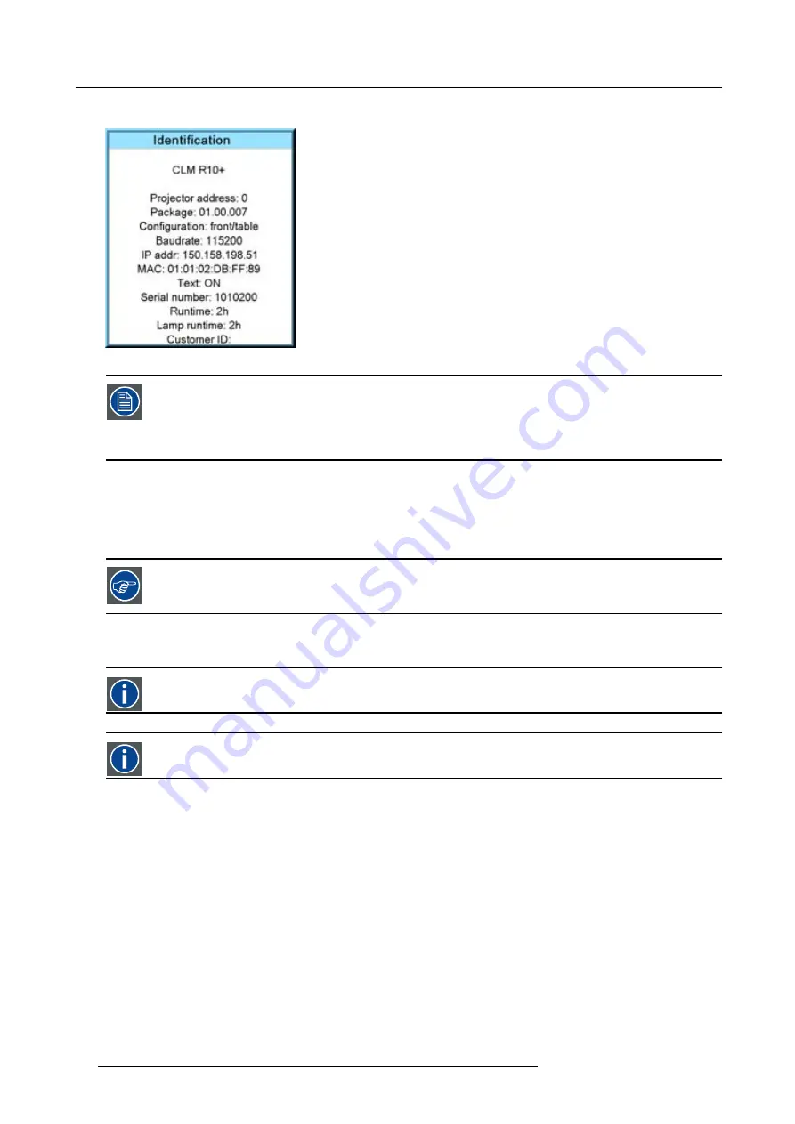
The projector’s address is displayed as
fi
rst item in the Identi
fi
cation screen.
Image 6-16
To continue using the RCU with that speci
fi
c address, it is necessary to enter the same address with the
digit buttons (address between 0 and 9) within 5 seconds after pushing the address key. For example : if the
Address key displays projector address 003, then press "3" digit button on the RCU to set the RCU’s address
to match the projector’s address. Do not press 003 digits. This will address the remote control to ’0’ and
control all projectors in the room. If the address is not entered within 5 seconds, the RCU returns to its default
address (zero address) and control all projectors in the room.
How to Program an Address into the RCU?
1. Press the
Address
key (recessed key on the RCU) with a pencil.
2. Enter the address with the digit buttons within 5 seconds after pushing the address key.
Note:
That address can be any digit between 0 and 9.
The LED on the remote control must lit up while pressing a digit key. Otherwise the address is not entered in
the remote control.
6.7.2
Controlling the projector
Projector address
Address installed in the projector to be individually controlled.
Common address
Projector will always execute the command coming from a RCU programmed with that common address.
Why a projector address ?
As more than one projector can be installed in a room, each projector should be separately addressable with an RCU or computer.
Therefore each projector has its own address.
Set up an individual Projector Address.
The set up of a projector address can be done via the software. See chapter ’Projector Control’, ’Projector address’.
Projector controlling.
Every projector requires an individual address between 0 and 255 which can be set in the Service mode.
When the address is set, the projector can be controlled now:
•
RCU for addresses between 0 and 9.
•
computer, e.g. IBM PC (or compatible), Apple MAC, etc. for addresses between 0 and 255.
54
R59770021 CLM R10+ 15/03/2010
Содержание CLM R10+ R9050100
Страница 1: ...CLM R10 Users manual R9050100 R90501001 R59770021 10 15 03 2010 ...
Страница 14: ...1 Safety 10 R59770021 CLM R10 15 03 2010 ...
Страница 22: ...2 General 18 R59770021 CLM R10 15 03 2010 ...
Страница 35: ...3 Physical installation Skew Image 3 28 Skew adjustment R59770021 CLM R10 15 03 2010 31 ...
Страница 36: ...3 Physical installation 32 R59770021 CLM R10 15 03 2010 ...
Страница 48: ...5 Connections 44 R59770021 CLM R10 15 03 2010 ...
Страница 64: ...7 Start up of the Adjustment mode 60 R59770021 CLM R10 15 03 2010 ...
Страница 74: ...8 Input menu 70 R59770021 CLM R10 15 03 2010 ...
Страница 115: ...10 Layout menu Image 10 61 Image 10 62 Image 10 63 Image 10 64 R59770021 CLM R10 15 03 2010 111 ...
Страница 116: ...10 Layout menu 112 R59770021 CLM R10 15 03 2010 ...
Страница 158: ...13 Projector control 154 R59770021 CLM R10 15 03 2010 ...
Страница 172: ...14 Service menu 168 R59770021 CLM R10 15 03 2010 ...
Страница 186: ...16 Servicing 182 R59770021 CLM R10 15 03 2010 ...
Страница 195: ...17 Projector covers removal and installation Image 17 18 Secure the lamp door R59770021 CLM R10 15 03 2010 191 ...
Страница 196: ...17 Projector covers removal and installation 192 R59770021 CLM R10 15 03 2010 ...
Страница 204: ...C DMX Chart 200 R59770021 CLM R10 15 03 2010 ...
Страница 210: ...D Specifications 206 R59770021 CLM R10 15 03 2010 ...
Страница 216: ...E Troubleshooting 212 R59770021 CLM R10 15 03 2010 ...
Страница 222: ...F Mounting optional Carry handle 218 R59770021 CLM R10 15 03 2010 ...
Страница 224: ...G Order info 220 R59770021 CLM R10 15 03 2010 ...
Страница 232: ...Index 228 R59770021 CLM R10 15 03 2010 ...


