background image

1

Balun

Distanziatori

Spacer Rod

Isolatore

Insulator

cod. 00023

Corda

Rope

Cavo d’antenna

Antenna’s cable

2

4

3

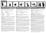
5.1) Inserire i moschettoni dell’antenna nelle asole 

1,2,3 e 4 (figura 1) 

5.2) Fissare i capocorda e stringere il galletto come 

in figura 4

5.1) Insert the carabiners of the antenna in slots 

1,2,3 and 4 (figure 1)

5.2) Fix the cable lugs and tighten the nut as shown 

4

6.0 ) CONNESSIONE 

6.1 ) Connettere il cavo coassiale all’antenna, a 

mezzo di un connettore N maschio, all’ elemento 

centrale (Balun)

6.0) CONNECTION

6.1) Connect the coaxial cable to the antenna, with 

a male N connector, to the central element (Balun)

BANTEN Via Santa Maria, 13 – 16042 CARASCO  ( Genoa ) ITALY   

www.banten.com


5.0) ASSEMBLAGGIO ANTENNA 

5.0) ANTENNA ASSEMBLY

ì

ì

Содержание WIDE BAND DIPOLE ANTENNA Series

Страница 1: ...TION MANUAL Dipole 1 5 28 MHz mt 15 150 W code 13013 Dipole 1 5 28 MHz mt 20 400 W code 13014 Dipole 1 5 28 MHz mt 30 1 Kw code 13012 Dipole 1 5 28 MHz mt 60 2 Kw code 13015 BANTEN Via Santa Maria 13...

Страница 2: ...8 2 Polar Diagram 9 0 COPYRIGHT dia 5 mm Polithene Jacket high resistant Silver plated copper braid Kevlar core Particolare dello speciale cavo di antenna con anima in Kevlar Detail of the special an...

Страница 3: ...lar core cable Silver plated copper braid Finitura Finishing PE insulation cover Colore Colour Black Frequenza Frequency 1 5 28 MHz Potenza Power Watt 150 400 1000 2000 Resistenza Resistance 860 800 7...

Страница 4: ...e with MIL T 704K BANTEN Via Santa Maria 13 16042 CARASCO Genoa ITALY www banten com 2 0 RECOMMENDATIONS The failure to observe the following recommenda tions and instructions may invalidate the value...

Страница 5: ...porto 1 pezzo The carrying bag closed 3 0 UNPACKING 3 1 Visual Inspection Check that the antenna original packaging is undamaged check that all components are in the package see 3 2 point and check th...

Страница 6: ...WR can be greatly influenced by the antenna s proximity to ground and other conductors The ideal mounting for the HF antenna is 2 to 5ft 0 5 1 5m above the ground or reference plane as far as possible...

Страница 7: ...carabiners of the antenna in slots 1 2 3 and 4 figure 1 5 2 Fix the cable lugs and tighten the nut as shown 4 6 0 CONNESSIONE 6 1 Connettere il cavo coassiale all antenna a mezzo di un connettore N m...

Страница 8: ...ion to 360 Irradiation lobe Configurazione Direttiva Inclinazione di circa 20 dell antenna diritta rispet to al suolo Si ottiene una configurazione di pendenza indica ta per avere un lobo di radiazion...

Страница 9: ...nstructions are Banten properties useful and necessary for the installation of antennas Banten duplication or copying even partial is prohibited without the express written consent 8 1 Diagramma Linea...

Отзывы: