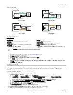
Wiring Diagrams
+
-
Output
Power
Supply
12–30 V dc
Output Common
VE Output
Load
VE
Figure 5. PNP Output
VE
+
-
12-30V dc
Output Common
VE Output
Load
Output
Power
Supply
Figure 6. NPN Output
+
-
Input
Power
Supply
VE Input
Input Common
PNP Driver
12–30 V dc
Opto-isolator
VE
Figure 7. PNP Input
+
-
VE
Input Common
Input
Power
Supply
NPN Driver
VE Input
Opto-isolator
12–30 V dc
Figure 8. NPN Input
Install the Software
PC Requirements
Operating System
Microsoft
®
Windows
®
operating system version 7, 8, or 102
System Type
32-bit, 64-bit
Hard Drive Space
80 MB (plus up to 280 MB for Microsoft .NET 4.5, if not already installed)
Memory (RAM)
512 MB minimum, 1 GB+ recommended
Processor
1 GHz minimum, 2 GHz+ recommended
Screen Resolution
1024 × 768 full color minimum, 1650 × 1050 full color recommended
Third-Party Software
Microsoft .NET 4.5, PDF Viewer (such as Adobe Acrobat)
USB Port
USB 3.0, recommended if a USB to Ethernet adapter used to communicate with the
sensor
Important: Administrative rights are required to install the Vision Manager software.
1. Download the latest version of the software from
2. Navigate to and open the downloaded file.
3. Click Next to begin the installation process.
4. Confirm the software destination and availability for users and click Next.
5. Click Install to install the software.
6. Depending on your system settings, a popup window may appear prompting to allow Vision Manager to make changes to your computer.
Click Yes.
7. Click Close to exit the installer.
Getting Started
Power up the sensor, and verify that the
power/error LED is ON green and that the Ethernet indicator is ON amber to verify the Ethernet
connection.
Connect to the Sensor
These instructions use Windows
®
operating system version 7, 8, or 10.
3
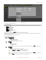
1. Confirm the network connections.
a) Click the Start button, then on the Start menu, click Control Panel.
b) In Control Panel, click Network and Internet, then click Network and Sharing Center, and then click Change adapter settings.
c) Right-click on the connection that you want to change, then click Properties.
If you are prompted for an administrator password or confirmation, enter the password or provide confirmation.
d) In the connection properties, click Internet Protocol Version 4 (TCP/IPv4), and then click Properties.
e) In the Internet Protocol (TCP/IPv4) Properties, select Use the following IP address.
f)
Make sure that the IP address is 192.168.0.2, and the subnet mask is 255.255.255.0.
2. Open Vision Manager from the desktop or the Start menu.
The Sensor Neighborhood tab displays and lists the available sensors.
2 Microsoft and Windows are registered trademarks of Microsoft Corporation in the United States and/or other countries.
3
Windows is a registered trademark of Microsoft Corporation in the United States and/or other countries.
VE Series Smart Camera
4
www.bannerengineering.com - Tel: +1-763-544-3164
P/N 191667 Rev. G


