background image

3. Apply power to all devices.
4. Form the wireless network by binding the Nodes to the Gateway. If the binding instructions are not included in the datasheet, refer to

the product manual for binding instructions.

5. Observe the LED behavior to verify the devices are communicating with each other.
6. Conduct a site survey between the Gateway and Nodes. If the site survey instructions are not included in this datasheet, refer to the

product manual for detailed site survey instructions.

7. Install your wireless sensor network components. If installation instructions are not included in this datasheet, refer to the product

manual for detailed installation instructions.

For additional information, including installation and setup, weatherproofing, device menu maps, troubleshooting, and a list of accesso-
ries, refer to one of the following product manuals.

• SureCross Wireless I/O Network Manual: 

132607

• Web Configurator Manual (used with "Pro" and DX83 models): 

134421

• Host Configuration Manual 

132114

Configuring the DIP Switches

Before making any changes to the DIP switch positions, disconnect the power. DIP switch changes will not be recognized if power isn't
cycled to the device.

Accessing the Internal DIP Switches

To access the internal DIP switches, follow these steps:

1. Unscrew the four screws that mount the cover to the bottom housing.
2. Remove the cover from the housing without damaging the ribbon cable or the pins the cable plugs into.
3. Gently unplug the ribbon cable from the board mounted into the bottom housing.
4. Remove the black cover plate from the bottom of the device's cover.

The DIP switches are located behind the rotary dials.

After making the necessary changes to the DIP switches, place the black cover plate back into position and
gently push into place. Plug the ribbon cable in after verifying that the blocked hole lines up with the missing
pin. Mount the cover back onto the housing.
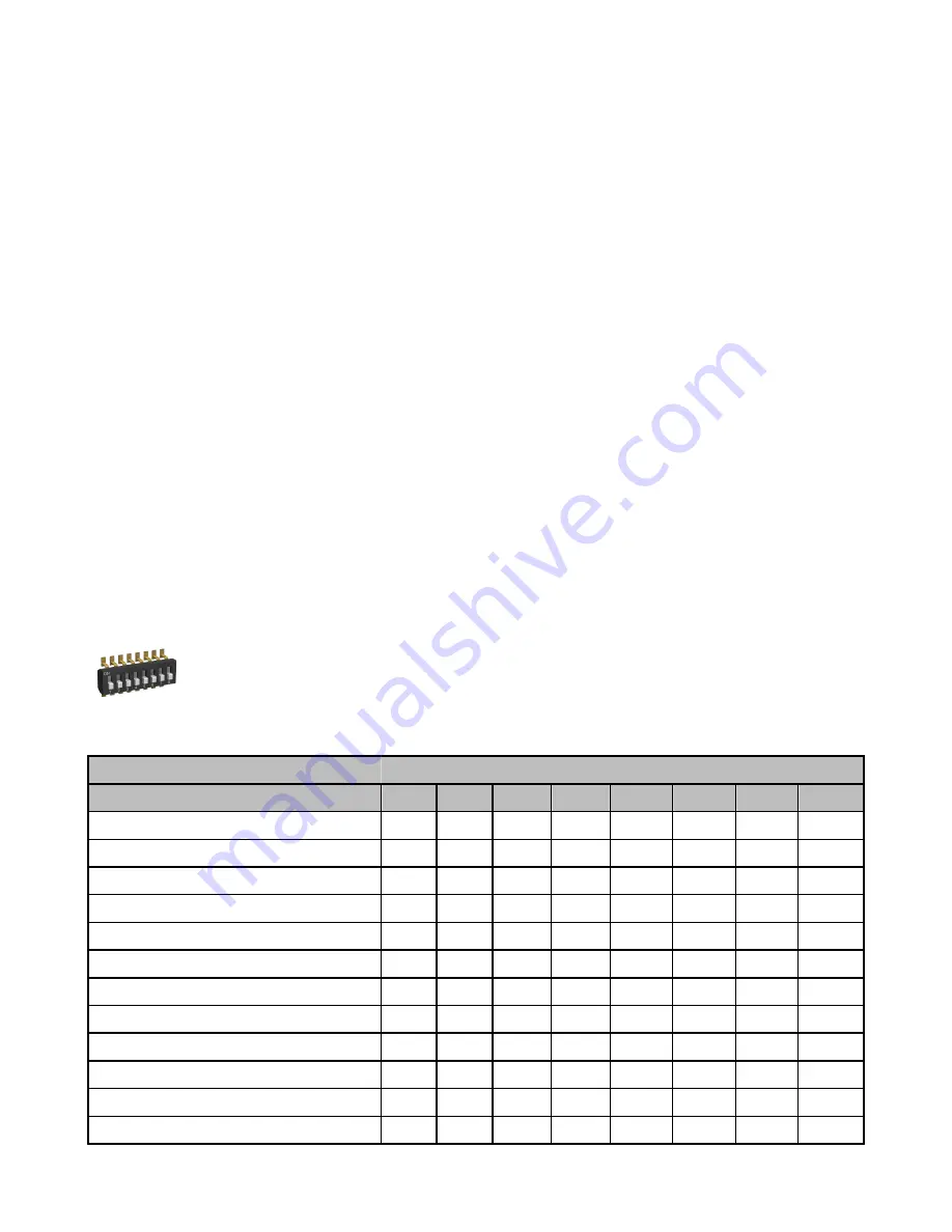
DIP Switch Settings

Switches

Device Settings

1

2

3

4

5

6

7

8

Rotary switch address mode

OFF*

Extended address mode

ON

Temp °Fahrenheit

OFF*

Temp °Celsius

ON

High resolution (0.1 degree)**

OFF*

Low resolution (1 degree)

ON

Discrete sinking inputs

OFF*

Discrete sourcing inputs

ON

Thermocouple, J-Type

OFF*

OFF*

OFF*

OFF*

Thermocouple, B-Type

OFF

OFF

OFF

ON

Thermocouple, C-Type

OFF

OFF

ON

OFF

Thermocouple, D-Type

OFF

OFF

ON

ON


SureCross DX99 FlexPower Thermocouple Node (Polycarbonate Housing)

2

www.bannerengineering.com - tel: 763-544-3164

P/N 142498 Rev. E

Содержание SureCross FlexPower DX99 Series

Страница 1: ...de the Canadian Electrical Code or applicable local codes regulations Model Frequency I O DX99N9X2S2N0T4X0A0 900 MHz ISM Band Inputs Two selectable discrete three thermocouple one thermistor for CJC DX99N2X2S2N0T4X0A0 2 4 GHz ISM Band Internal antenna models are also available For more information contact your local Banner Engineering Corp representative WARNING Not To Be Used for Personnel Protec...

Страница 2: ...ot be recognized if power isn t cycled to the device Accessing the Internal DIP Switches To access the internal DIP switches follow these steps 1 Unscrew the four screws that mount the cover to the bottom housing 2 Remove the cover from the housing without damaging the ribbon cable or the pins the cable plugs into 3 Gently unplug the ribbon cable from the board mounted into the bottom housing 4 Re...

Страница 3: ...on To use extended address mode change the DIP switch to the ON position Discrete Input Type Select the type of discrete input sensors to use with this device sourcing PNP sensors or sinking NPN sensors Modbus User Configuration Tool UCT or DIP Switch Configured In Modbus UCT Configured mode the device parameters are changed using the User Configuration Tool UCT or a Modbus command All DIP switch ...

Страница 4: ...I1 GND Ax and Ax Analog IN x Analog inputs for devi ces requiring more than one connection such as thermocouples or RTDs When there is no Ax use Ax as an analog input DIx Discrete IN x GND Ground dc common connection 1 2 3 4 5 FlexPower 3 blue dc common GND 5 gray 3 6V dc Only use the DX81H Bat tery Supply Module to power this device LED Behavior for the Nodes After powering up and binding the Gat...

Страница 5: ...exPower or integra ted battery SureCross radio into storage mode press and hold button 1 for five seconds The radio is in storage mode when the LEDs stop blinking but in some models the LCD remains on for an additional minute after the radio enters storage mode After a device has entered storage mode you must wait one minute before waking it During normal operation the SureCross radio devices ente...

Страница 6: ...95 max relative non condensing Radiated Immunity 10 V m 80 2700 MHz EN61000 6 2 Shock and Vibration IEC 68 2 6 and IEC 68 2 7 Shock 30g 11 millisecond half sine wave 18 shocks Vibration 0 5 mm p p 10 to 60 Hz Refer to the SureCross DX80 Wireless I O Network Product Manual p n 132607 for installation and waterproofing instructions Operating the devi ces at the maximum operating conditions for exten...

Страница 7: ...ries using the antenna that ships with the product When using other antennas verify you are not exceeding the transmit power levels allowed by local governing agencies Consult with Banner Engineering Corp if the destination country is not on this list Violating Warnings The manufacturer does not take responsibility for the violation of any warning listed in this document Make no modifications to t...

Страница 8: ... STRICT LIABILITY NEGLIGENCE OR OTHERWISE Banner Engineering Corp reserves the right to change modify or improve the design of the product without assuming any obligations or liabilities relating to any product previously manufactured by Banner Engineering Corp SureCross DX99 FlexPower Thermocouple Node Polycarbonate Housing www bannerengineering com tel 763 544 3164 ...

Отзывы:

Похожие инструкции для SureCross FlexPower DX99 Series