


P/N 69761 rev. B
11
Banner Engineering Corp.
•
Minneapolis, U.S.A.
www.bannerengineering.com • Tel: 763.544.3164
PICO-GUARD Controller
Instruction Manual
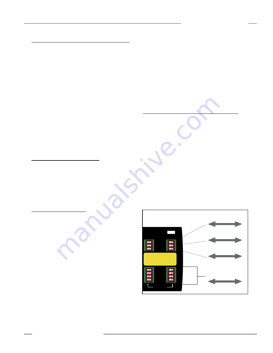
Auto
Power-up
Manual
Power-up
Trip
Output
Latch
Output
1-Channel
EDM
2-Channel
EDM
OFF
ON
Optical Channels
Configuration
Auto/Man
Trip/Latch
1 / 2 E D M
1 Off/On
2 Off/On
3 Off/On
4 Off/On
A
B
Channel
Figure 3-6. Configuration DIP switches
3.7.1 External Stop Device Requirements/Hookup
Refer to Figures 3-7, 3-8, 3-9 and 3-10 for detailed hookup
information.
For external stop devices with contact outputs, the contacts
must be redundant and capable of switching 15-30V dc @
10-50 mA. Contacts must switch simultaneously (within 3
seconds of each other). For
USSI
1 connection, connect one
contact output of the external stop device between PICO-
GUARD controller terminals 2-3, and the other contact output
between terminals 4-5. For
USSI
2 connection, connect one
contact output of the external stop device between PICO-
GUARD controller terminals 7-8, and the other contact output
between terminals 9-10.
NOTE: For external stop devices with solid-state outputs, the
outputs must be Banner Engineering safety devices
with “handshake” verification. Connect the compatible
solid-state outputs to terminals 2 and 4 for
USSI
1
connection, or terminals 7 and 9 for
USSI
2 connection.
0V dc must be common between the external stop
device and the PICO-GUARD controller (terminal 20).
3.7.2 Other PICO-GUARD Modules
PICO-GUARD controllers may be connected together in
applications where more than four optical channels are
needed. Connect the OSSD 1 and OSSD 2 outputs of one
PICO-GUARD controller to the appropriate
USSI
input of
another PICO-GUARD controller as shown in Figure 3-10.
0V dc must be common between the external stop device
and the PICO-GUARD controller (terminal 20).
3.8 Initial System Checkout
The initial checkout procedure must be performed by a
Qualified Person (see Section 3.2). It must be performed
only after configuring the System and after installing and
connecting the optical elements per the applicable instructions
and standards.
The procedure is performed on two occasions:
• To ensure proper installation when the System is first
installed, and
• To ensure proper System function whenever any maintenance
or modification is performed on the System or on the
machinery being guarded by the System. (See Section 6.1 for
a schedule of required checkouts.)
For the initial checkout, the PICO-GUARD System must
be checked without power being available to the guarded
machine.
Final interface connections to the guarded
machine cannot take place until the system has been
checked out.
Verify that:
• Power has been removed from (or is not available to) the
guarded machine, its controls or actuators; and
• The machine control circuit is not connected to the OSSD
outputs at this time (permanent connections will be made
following this initial checkout)
• If the inputs are to be used, verify the system(s) checkout
procedures for the external safety systems or other devices
connected to the external stop device inputs as described by
the appropriate manuals.
Do not proceed until all checkout
procedures are completed successfully and all problems
have been corrected.
3.8.1 Configure the Controller for Initial Checkout
Controller configuration is done at the two banks of DIP
switches located under the clear access cover on the right side
of the controller (see Figure 3-6). Verify that the system is set
for initial checkout and optical alignment (Manual Power-Up,
Latch, 2-Channel EDM and All used Optical Channels ON,
unused Optical Channels OFF. If changes to the DIP switch
settings are needed, see Section 4.2 for details.)
• Temporarily connect a jumper (supplied) between EDM 1 b
(terminal 13) and EDM 2 b (terminal 15) to configure EDM
for No Monitoring.
• Apply power to the controller. The System Reset indicator
should be double flashing.
• Perform a system reset (close the System Reset switch
for 1/4 to 2 seconds, then open it; see Section 4.3). The
System Reset indicator should go OFF and the System Status
indicator should come ON (Red or Green).
Installation and Alignment


