9. Verify that the Banner ABR Ethernet Module is connected by making sure that there is not a yellow warning symbol
over the module icon in the Controller Organizer. If there is no symbol, the ABR has a live connection to the PLC.
Figure 88. Icon—No Errors
10. Go to Controller tags and verify that the LastItemSeqNum tag is incrementing every time the reader sends a result
message.
11. If the tag is not incrementing, and the module showed a good connection in step 10, make sure that the reader is in
run mode or monitor mode. If it is, your AOI should be fully functional and receiving all the useful implicit messaging
data from the ABR.
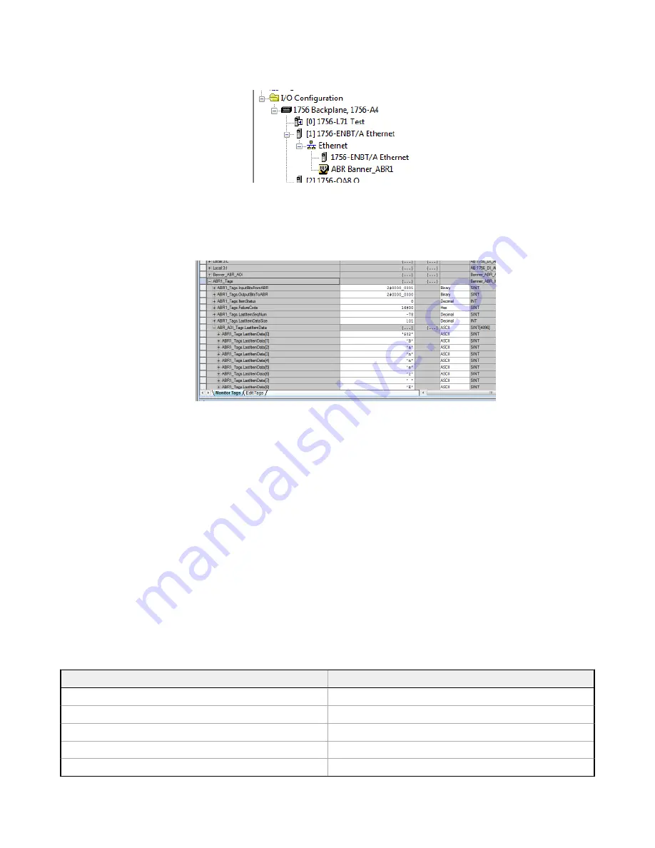
Figure 89. AOI Data Tags
8.2.6 AOI Data Description
The AOI’s data, all contained in one User-Defined data type (UDT) tag array, contains the data tags described in the
following sections.
InputBitsFrom
ABR
The Input Bits tag is a bitmap used to read the state of the 8 discrete inputs from the ABR reader. These should update live
to always show the latest result, even if the PLC is not caught up at transferring all the result messages.
OutputBitsTo
ABR
The Output Bits attribute is a bitmap used to control the state of the 8 discrete outputs to the ABR reader. This can be used
to trigger the reader by setting to 1 the bit ABR1_Tags.OutputBitsToABR.0, for example, as described in
Industrial Ethernet
Reading Phase Control
on page 48.
ItemStatus
The Item Status Code is the status of the last reading attempt and is always updated live regardless of whether the PLC has
finished receiving all the fragments of the previous message. The following table shows the status codes and their
meanings.
Item Status Code
Item Status Name
0×0000
Good Read
0×0001
Complete, No Read
0×0002
Partial Read
0×0003
Multiple Read
0×0004
Wrong Read
ABR 3000 Series Barcode Reader
66
www.bannerengineering.com - Tel: + 1 888 373 6767


