background image

8


P/N 118000 rev. A

Banner Engineering Corp. 

• 

Minneapolis, MN U.S.A.

www.bannerengineering.com  •  Tel: 763.544.3164

Software Setup

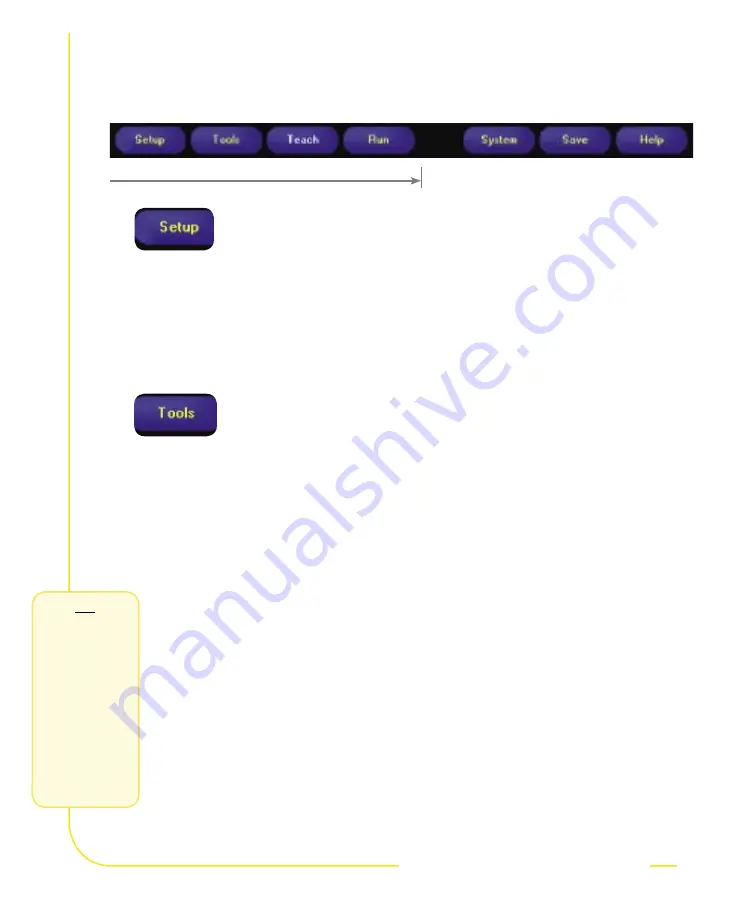
Use the Main Menu toolbar to navigate the PresencePLUS P4 options. Proceeding from left to 

right, the buttons in the Menu toolbar step through the process of creating an inspection file.

Inspection Work Flow

step 6

step 6

Add tools to the inspection. Build the tools from scratch or add tools from 

a previous inspection file saved on the PC or the Sensor. To add a Vision 

tool, click the Tool button. To remove a tool, click the “X” in the lower left 

corner of the screen.

a.   

Add 

Location tool(s)

 to find the target to adjust the following Regions of 

Interest (ROI) for transitional and rotational changes.

b. 

Add 

Vision tool(s)

 to inspect the part.

c.   

Add 

Measure tool(s)

 to create distance measurements from points 

found.

d.   

Add 

Test tool(s)

 to set the Pass/Fail criteria. (The Vision and Measure 

tools are inputs to the Test tool.)

 NOTES:

 •  

Click 

Quick Teach

 to automatically set all the selected parameters 

in the Test tool and proceed to the Run screen, or click 

Next


to proceed to the Teach screen, to teach a sample set of good 

products.


•  

If you want to keep parameters in a Test tool, skip 

Teach

 and go 

directly to 

Run

.

Set up the Sensor, lens, and lighting, to acquire a reference image.

a. 

Set up the Sensor lens and lighting.

b.  

Choose Trigger option 

Continuous

 for a live image.

c. 

Click

 Auto Exposure

 to adjust the brightness.

d.   

Focus the Sensor lens by turning the lens until the Focus Number is 

maximized.

Required

Required

1.

2.

creating

inspections

creating

inspections

TIPS

Before creating an 

inspection file, set 

up the electrical 

configuration 

of the external 

trigger. (Click 

System

 button, 

select 

Trigger

 tab.)

Содержание PresencePlus P4 EDGE

Страница 1: ...Printed in USA 12 04 P N 118000 rev A Models included GEO EDGE...

Страница 2: ...t circuitry necessary to allow its use in personnel safety applications A sensor failure or malfunction can cause either an energized or de energized sensor output condition Consult your current Banne...

Страница 3: ...is not required for running inspections after the inspection files have been stored in the Sensor s memory Start Hook Up the Hardware Install the Software and Establish Communications Acquire an Imag...

Страница 4: ...le to the NTSC Video monitor connector 3 Connect the Ethernet cable from your PC to the Sensor at the RJ 45 connector a If connecting directly from the PC use a crossover cable b If connecting the Sen...

Страница 5: ...ete I O 3 In Out 8 Light Blue Discrete I O 4 In Out 9 Violet RS 232 RX Input 10 Green RS 232 Signal Ground Output 11 Blue Common Signal Ground Input 12 Brown 10 30V dc Input TIPS The trigger device ca...

Страница 6: ...CD b Click Install PresencePLUS Software a Right mouse click on Network Neighborhood and select Properties b Open the TCP IP Properties under the Protocols tab c Change the IP address to 192 168 0 2...

Страница 7: ...back cover for part number for detailed instructions on serial port configuration 3 If using an optional NTSC video monitor verify that the monitor is displaying an image 4 When the software launches...

Страница 8: ...part c Add Measure tool s to create distance measurements from points found d Add Test tool s to set the Pass Fail criteria The Vision and Measure tools are inputs to the Test tool NOTES Click Quick T...

Страница 9: ...ompensates for translation and rotation Locate Translation and rotation Finds the edge of the part and compensates for translation and rotation if selected Vision Tools GEO Count Finds one or more pat...

Страница 10: ...via Product Change and Product Select lines TIPS When using the Hardware input pulse the Product Change and Product Select inputs to initiate an inspection change See User s Manual for complete inform...

Страница 11: ...7 System Setup Use the System Setup screen to change discrete I O the communication port the product change the strobe output for external lighting control the trigger input and to view diagnostic inf...

Страница 12: ...of neutral detergent Avoid getting dirt on the Sensor s imager the area behind the lens If the imager is dirty use anti static compressed air to blow off the dust Cleaning the Sensor Lens Regularly re...

Страница 13: ...e try again Image is frozen on PC and monitor Sensor Power Error LED is Red Software restart needed or loose connections Restart the PresencePLUS software If the connections are secure call a Banner A...

Страница 14: ...29 kg 0 642 lb Environmental Rating IEC IP20 NEMA 1 Operating Temperature 0 C to 50 C 32 F to 122 F Maximum Relative Humidity 90 non condensing Display Options PC or NTSC video 9 m 30 max cable lengt...

Страница 15: ...tage 10 30V dc Current 500 mA max Acquisition 500 frames per second max Image size 126 x 98 pixels Levels of Gray Scale 256 Imager 2 56 x 2 06 mm 3 25 mm diagonal CMOS Pixel Size 20 x 20 microns Expos...

Страница 16: ...ering com Email sensors bannerengineering com P N 118000 rev A Models Tools PresencePLUS P4 Models User s Manual Part Number Tools Locate GEO Find GEO Count Edge Object Measure Test Comm GEO 117020 X...

Отзывы: