background image

1.4

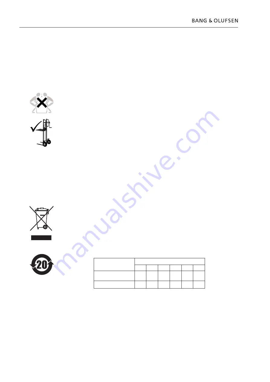
How to handle heavy products

As a Bang & Olufsen technician you are responsible for repair and service of 
heavy Bang & Olufsen products. Below we have listed some useful tips on how 
you may handle heavy products.

Tips for correct handling of heavy products

You must familiarize yourself with national handling regulations and 
recommendations as these differ worldwide. 

Video products are too heavy to be lifted manually. Make sure that you use proper 
lifting methods and equipment when it is necessary to move the products. Or use 
trained personnel or partners to carry out the lifting in a safe manner. 

Always use the product cover when you transport the product to avoid damages.

Always lift the product in an upright position and avoid putting pressure on the 
screen. Please refer to the documentation with the product or stands/wall brackets 
for specific advice.

You must support the product until it is mounted on a wall bracket or stand since 
it cannot stand on its own.

You must not move the product when it is switched on. Please make sure that the 
product is completely disconnected from the mains before moving it.

Waste of Electrical and Electronic Equipment (WEEE)

Electrical and electronic equipment, parts and batteries marked with this symbol 
must not be disposed of with normal household wastage; all electrical and 
electronic equipment, parts and batteries must be collected and disposed of 
separately.
Your Bang & Olufsen retailer will advise you of the correct way of disposal in your 
country.

Management methods for controlling pollution caused by Electronic Information Products

Component
name:

Hazardous substance

Pb

Hg

Cd

Cr(VI)

PBB

PBDE

Aluminum parts

×

o

o

o

o

o

PCBA

×

o

o

o

o

o

Symbols used in the charts:

o

  Indicates all homogeneous materials’ hazardous substances content are below the 

ST/T 11363–2006 MCV limit.

× 

Indicates that the hazardous substance content contained in any one of the 
homogeneous materials of the part exceeded the MCV limits specified in the 
standard SJ/T 11363-2006.

Содержание BeoVision 10-40

Страница 1: ...ion 10 46 Type 9565 Service Manual English German French Italian Spanish Danish Dutch and Simplified Chinese versions are available in the Retail System This Service Manual must be returned with the d...

Страница 2: ...ervice 1 2 Fault flow chart 2 1 Adjustments 3 1 ServiceTool 3 8 Final check after repair 3 9 Service Mode 4 1 Replacement of modules 5 1 Specification guidelines for service use 6 1 Block diagram 7 1...

Страница 3: ...CB01 Tuner PCB04 Power Supply PCB10 Audio PCB11 IR Receiver PCB12 Filter PCB14 Main PCB21 Engine f DVB HD PCB22 Front End f DVB HD PCB32 DSM PCB51 System Module PCB59 Camera PCB61 BtB Optional FAN 04...

Страница 4: ...ion must be made in the Retail Order System Exchange Module BeoVision 10 can be serviced hanging on the wall bracket or on the floor stand Service stand can be mounted Connect the mains cable to the B...

Страница 5: ...to the static protective field service kit or placed in an ESD proof bag Symbol of safety components When replacing components with this symbol the same type has to be used also the same values for o...

Страница 6: ...it is mounted on a wall bracket or stand since it cannot stand on its own You must not move the product when it is switched on Please make sure that the product is completely disconnected from the mai...

Страница 7: ...on internal speakers 2 9 No sound in headphones Power Link and internal speakers when using HDMI input 2 10 No sound output in headphones Power Link and internal speakers when using AV1 2 10 No sound...

Страница 8: ...rn off Confirm voltages on PCB14 Main J1 pin 1 2 3 4 5 12V J1 pin 15 12V and on PCB04 Power Supply CN202 pin 1 24V All OK Replace PCB04 Power Supply Check backlight ON Confirm voltages on PCB04 Power...

Страница 9: ...Possible causes PCB11 IR Receiver PCB12 Filter PCB14 Main Check connection between PCB11 IR Receiver and PCB14 Main OK Replace PCB14 Main Replace PCB11 IR Receiver Check that Light Sense is ON in the...

Страница 10: ...video signal from tuner RF Possible causes PCB01 Tuner Replace cable or re establish connection Replace PCB01 Tuner Connect a video source to AV2 CVBS 1 Press MENU 2 Select CONNECTIONS 3 Select AV2 4...

Страница 11: ...CONNECTIONS 3 Select AV2 4 Remember the selected source button e g V AUX 5 Set HDMI OFF 6 Set YPbPr OFF 7 Press the selected source button e g V AUX Picture OK Confirm that J14 is connected to PCB51...

Страница 12: ...onfirm that backlight is on Re establish connection or replace cable Confirm 24 V on PCB04 Power Supply CN202 pin 1 GND pin 6 Replace PCB14 Main Replace PCB04 Power Supply Replace LCD panel Confirm 3...

Страница 13: ...3 CVBS Possible causes PCB14 Main Connect a signal source to AV3 D SUB VGA or HDMI 1 Press MENU 2 Select CONNECTIONS 3 Select AV3 4 Remember the selected source button e g PC 5 Set HDMI A or B if used...

Страница 14: ...M P13 Pin 4 5 12V Pin 2 GND All OK Check connection between PCB14 Main and PCB32 DSM OK Replace cable or re establish connection Replace PCB14 Main Flash update DSM FEP and DSM DSP Sound OK Yes Does L...

Страница 15: ...PCB32 DSM Confirm signal on PCB10 Audio JA3 Pin 6 8 Pin 7 GND OK Replace PCB14 Main Check that the five internal speakers are OK with use of an ohm meter OK 3 6ohm can be mesured on PCB10 Audio on JA...

Страница 16: ...sound output on Power Link Check sound output on internal speakers OK Go to page 2 9 No sound output on internal speakers Replace PCB14 Main Maybe audio matrix fault Replace PCB51 System Module Connec...

Страница 17: ...S 3 Select AV3 4 Remember the selected source button e g VMEM 5 Set HDMI OFF 6 Set VGA OFF 7 Press the selected source button e g VMEM Confirm audio output on AV2 R pin 1 L pin 3 GND pin 4 OK No Yes C...

Страница 18: ...an audio source to AV3 L R and continue on with the following 1 Press MENU 2 Select CONNECTIONS 3 Select AV3 4 Remember the selected source button e g DVD 5 Set HDMI OFF 6 Set VGA OFF 7 Press the sele...

Страница 19: ...g AV1 Replace PCB14 Main May be audio matrix Connect an audio source to AV1 R L and continue on with the following 1 Press MENU 2 Select CONNECTIONS 3 Select AV1 4 Remember the selected source button...

Страница 20: ...Cable OK Fault symptom No control of set top box using STB C PUC Possible causes PCB14 Main Replace PCB14 Main Replace IR Remote Cable Connect ServiceTool update software to newest version OK Update...

Страница 21: ...ule is in use for instance in a hotel setup it is necessary to press MENU 0 0 GO on the remote control to disable the Hotel Menu Within 5 seconds press MENU 0 0 GO once more to enter Service Menu and...

Страница 22: ...2 16 2 16 2 16...

Страница 23: ...Menu 3 3 Geometry adjustment 3 3 Geometry specifications 3 4 Picture adjustments 3 5 Default factory values 3 5 Speaker adjustments 3 7 Access to adjustment points 3 7 Speaker adjustment table 3 7 Se...

Страница 24: ...ntrast and colour can only be adjusted in the menu PICTURE The SERVICE MENU does not give this opportunity Measurements For the best result measurements are performed in a straight angle to the LCD pa...

Страница 25: ...top Modified data is not saved p Moves the cursor down Selects a submenu in some cases l Modifies data n Modifies data STOP Backs up through menus 0 9 Digit Modifies data EXIT Exits all menus Geometry...

Страница 26: ...3 4 Adjustments Geometry specifications Format 1 16 9 Panorama Format 1 15 9 Format 1 4 3 Format 2 16 9 Letterbox Format 3 Real 16 9...

Страница 27: ...ent of the specific parameters is not described Picture settings TV MENU PICTURE Brightness Contrast Colour Middle position Middle position Middle position Picture adjustments 1 Check the picture qual...

Страница 28: ...002 002 002 002 2 2 Film sensitivity 002 002 002 002 002 Pixel boost 000 000 000 000 000 DCS 000 000 000 000 000 DCTI 001 001 001 001 001 Peaking 002 007 010 009 014 Spatial noise filter 007 004 003...

Страница 29: ...Audio module must be adjusted accordingly Adjustment must be performed when either speaker unit or Audio module is replaced Access to adjustment points Set BeoVision 10 in service position See page 5...

Отзывы: