


50
60
70
80
90
100
110
120
130
140
150
Distance from centre of disc to stylus (mm)
150
200
250
300
350
400
450
500
550
Rotational velocity (mm/sec)
12" 33 1/3 RPM
7" 45 RPM
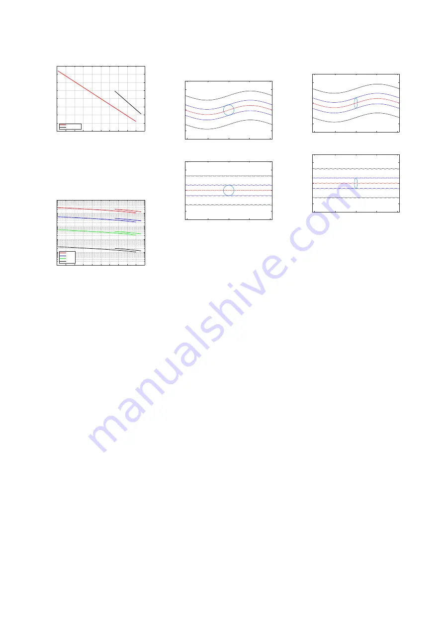
Figure 3.11: The relative speed of the
stylus to the surface of the vinyl as it
tracks from the outside to the inside ra-
dius of the record.
50
60
70
80
90
100
110
120
130
140
150
Stylus distance from centre of disc (mm)
0.001
0.01
0.1
1
10
100
Wavelength (mm)
20 Hz
100 Hz
1 kHz
20 kHz
Figure 3.12: The wavelengths measured
in the groove, as a function of the sty-
lus’s distance to the centre of a disc.
The shorter lines are for 45 RPM 7“discs,
the longer lines are for 33 1/3 RPM 12“
LPs.
However, now we have a problem. If
the “wiggles” in the groove have a
total wavelength of 11
µ
m, but the tip
of the stylus has a diameter of about
36
µ
m, then the stylus will not be able
to track the groove because it’s simply
too big (just like the tires of your car do
not sink into every small crack in the
road). Figure
shows to-scale
representations of a conical stylus with
a diameter of 36
µ
m in a 70
µ
m-wide
groove on the inside radius of a 33 1/3
RPM LP (60 mm from the centre of the
disc), viewed from above. The red lines
show the bottom of the groove and the
black lines show the edge where the
groove meets the surface of the disc.
The blue lines show the point where
the stylus meets the groove walls. The
top plot is a 1 kHz sine wave and the
bottom plot is a 20 kHz sine wave, both
with a lateral modulation velocity of 70
mm/sec. Notice that the stylus is
simply too big to accurately track the
20 kHz tone.
-100
-50
0
50
100
Groove length (µm)
-50
0
50
Lateral Position (µ
m)
-100
-50
0
50
100
Groove length (µm)
-50
0
50
Lateral Position (µ
m)
Figure 3.13: Scale representations of a
conical stylus with a diameter of 36
µ
m
in a 70
µ
m-wide groove on the inside
radius of a 33 1/3 RPM LP, looking di-
rectly downwards into the groove. See
the text for more information.
One simple solution was to “sharpen”
the stylus; to make the diameter of the
spherical tip smaller. However, this can
cause two possible side e
ff
ects. The
first is that the tip will sink deeper into
the groove, making it more di
ffi
cult for
it to move independently on the two
audio channels. The second is that the
point of contact between the stylus
and the vinyl becomes smaller, which
can result in more wear on the groove
itself because the “footprint” of the tip
is smaller. However, since the problem
is in tracking the small wavelength of
high-frequency signals, it is only
necessary to reduce the diameter of
the stylus in one dimension, thus
making the stylus tip
elliptical
instead
of conical. In this design, the tip of the
stylus is wide, to sit across the groove,
but narrow along the groove’s length,
making it small enough to accurately
track high frequencies. An example
showing a 0.2 mil x 0.7 mil (10 x 36
µ
m) stylus is shown in Figure
.
Notice that this shape can track the 20
kHz tone more easily, while sitting at
the same height in the groove as the
conical stylus in Figure
-100
-50
0
50
100
Groove length (µm)
-50
0
50
Lateral Position (µ
m)
-100
-50
0
50
100
Groove length (µm)
-50
0
50
Lateral Position (µ
m)
Figure 3.14: Scale representations of an
elliptical stylus with diameters of 10 x
36
µ
m in a 70
µ
m-wide groove on the
inside radius of a 33 1/3 RPM LP, look-
ing directly downwards into the groove.
See the text for more information.
Both the conical and the elliptical
stylus designs have a common
drawback in that the point of contact
between the tip and the groove wall is
extremely small. This can be seen in
Figure
, which shows various stylus
shapes from the front. Notice the
length of the contact between the red
and black lines (the stylus and the
groove wall). As a result, both the
groove of the record and the stylus tip
will wear over time, generally resulting
in an increasing loss of high frequency
output. This was particularly a problem
when the CD-4 Quadradisc format was
introduced, since it relies on signals as
high as 45 kHz being played from the
disc. In order to solve this problem, a
new stylus shape was invented by
Norio Shibata at JVC in 1973. The idea
behind this new design is that the
sides of the stylus are shaped to follow
a much larger-radius circle than is
possible to fit into the groove,
however, the tip has a small radius like
a conical stylus. An example showing
this general concept can be seen on
the right side of Figure
.
11


