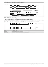
Device description • Operating and connection elements
78
Power Panel C70 User's manual V1.30
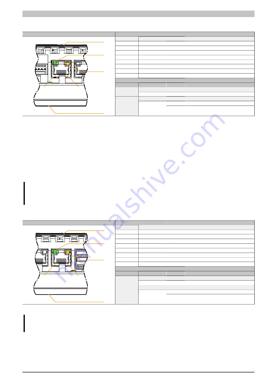
3.6.3 POWERLINK interface (IF1)
Figure
Pinout
Terminal
Ethernet
1
RXD
Receive data
2
RXD\
Receive data\
3
TXD
Transmit data
4
Termination
5
Termination
6
TXD\
Transmit data\
7
Termination
8
Termination
Diagnostic LEDs
LED
Color
Status
Description
Link
LNK
Green
On
Link established to Ethernet network.
Activity
On
No Ethernet activity taking place.
8
1
Front (touch screen)
LNK
ACT
Back
ACT
Orange
Blinking
Ethernet activity taking place (data being
transferred).
POWERLINK V2 mode
By default, the POWERLINK interface is operated as a managing node (MN). In the managing node, the node
number is set to a fixed value of 240.
If the POWERLINK node is operated as a controlled node (CN), a node number from 1 to 239 can be set in the
POWERLINK configuration in Automation Studio.
Ethernet mode
In this mode, the interface is operated as an Ethernet interface. The INA2000 node number is set using the B&R
Automation Studio software.
Information:
If interface IF1 is operated in Ethernet mode, then this interface receives its own IP address and works
independently of Ethernet interface IF2.
3.6.4 Ethernet interface (IF2)
Figure
Pinout
Terminal
Ethernet
1
RXD
Receive signal
2
RXD\
Receive signal inverted
3
TXD
Transmit signal
4
Termination
5
Termination
6
TXD\
Transmit signal inverted
7
Termination
8
Termination
Diagnostic LEDs
LED
Color
Status
Description
Link
LNK
Green
On
Link established to Ethernet network.
Activity
On
No Ethernet activity taking place.
8
1
Front (touch screen)
LNK
ACT
Back
ACT
Orange
Blinking
Ethernet activity taking place (data being
transferred).
The INA2000 node number is set with Automation Studio.
Information:
This Ethernet interface (IF2) is not suitable for POWERLINK.
Содержание VICPAS C70 Series
Страница 2: ...1393929349551 1 30 2019 02 14...


