


Maintenance / Service • Installing the UPS module
Chapter 7
Maintenance / Service
Automation PC 810 with GM45 CPU board user's manual V1.28
391
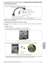
7.2.2 APC810 2 and 3 card slot
1. Remove the side cover (see "Mounting the side cover" on page 397).
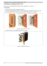
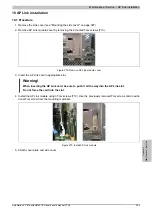
2. Remove UPS module cover by removing the 2 marked Torx screws (T10).
Figure 253: Removing the UPS module cover
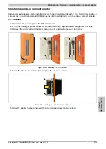
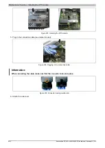
3. Screw in spacing bolt (using M5 hex socket screwdriver).
14 mm spacer bolts
Figure 254: Screw in spacing bolt
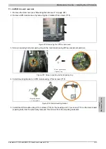
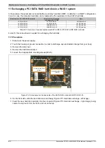
4. Install mounting bracket on UPS module using 2 Torx screws (T10).
Mounting bracket
+ 2 Torx screws
Figure 255: Install mounting bracket
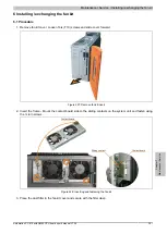
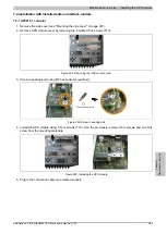
5. Install the UPS module using 3 Torx screws (T10). Use the previously removed Torx screws and one Torx
screw from the mounting materials.