background image

Bandit

120

Copyright 9/18

MODEL 15XP/1390

1

2

3

4

6

7

8

9

10

11

12

13

6

6

6

7

9

TYPICAL FEEDWHEEL CONTROL VALVES

TYPICAL SPRING LOADED CONTROL VALVE

11

9

8

4,12

6

6

7

2

1,12

3,12

6

6

7

10

HYDRAULIC COMPONENTS

Parts may not be exactly as shown.

NOTICE

Содержание INTIMIDATOR 15XP/1390

Страница 1: ...ht 9 18 ATTENTION Depending on what replacement parts you are ordering we will need the following information CHIPPER COMPONENTS Serial Number Model Number of Chipper ENGINE COMPONENTS Brand Engine Se...

Страница 2: ...ings ca gov diesel Respirar gases de escape de motores diesel le expone a qu micos conocidos por el estado de California como causales de c ncer y defectos cong nitos u otros da os reproductivos Para...

Страница 3: ...Bandit Industries Inc Safety Booklet D A N G E R ACCIDENTS INVOLVING BRUSH CHIPPERS CAN AND SHOULD BE PREVENTED Operator training and enforcement of safety policies are ESSENTIAL...

Страница 4: ...ded These meetings are a benefit to new inexperienced employees and also remind experienced employees of the obvious dangers involved with tree work Even experienced employees may be injured if they m...

Страница 5: ...he material Feeding from the side also positions the operator further from the feedwheels If you or your employees are not following these instructions a very serious accident could occur There is no...

Страница 6: ...hese kits are available from your local Bandit dealer SAFETY FEATURE WOODEN PUSH AND PADDLE MOUNT Update Kit UK 1008 WOODEN PUSH PADDLE AND MOUNT 980 0507 42 19 Wide Paddle 981 1005 30 22 Wide Paddle...

Страница 7: ...padlocked SAFETY FEATURE SPRING LOCK FOR HOOD PIN Update Kit UK 1009 SPRING LOCK FOR HOOD PIN Since September 1998 mechanical feed hand fed Bandit Chippers have been built with a plug in device on the...

Страница 8: ...ctric parts The system typically consists of two simple cables hanging inside the infeed hopper and in front of the feedwheels approximately halfway between the entrance of the infeed hopper and the f...

Страница 9: ...e material and re feed it back into the infeed hopper If the wood material is too big or limby back it out trim it and re feed it in portions NEVER fight or wrestle with limbs or branches Forcing mate...

Страница 10: ...make the chipper vibrate excessively causing machine fatigue damage and the engine to use more fuel Keep the knives sharp and the chipper will work smoother feed wood easier and make a safer operatio...

Страница 11: ...r turn the chipper disc drum by hand Always use a pry bar or wood bar This will prevent the person turning the disc drum from being injured should the disc drum break loose 8 Reinstall the discharge c...

Страница 12: ...ANSI and OSHA standards DANGER REFLECTIVE STRIPED TAPE ON FEED CONTROL HANDLE We began installing striped reflective tape on the feed control handle of our hand fed chippers This tape is reflective se...

Страница 13: ...e of the chipper must be familiar understand and follow instructions on the decals Decals are available in a variety of languages via Bandit dealers or factory Correct Installation and Care of Decals...

Страница 14: ...quent reminder as to the proper safe operation of any piece of equipment especially a chipper that is designed to quickly break down material much tougher than human flesh Please meet with your employ...

Страница 15: ...ived instruction and fully understands that the operators must always be located within easy reach of all feed control and shut down devices 6 _____ The customer has received instruction and fully und...

Страница 16: ...as ordered ________________________________________________ 5 Did all welds appear to be high quality ______________________________________________ 6 Was the overall machine to your liking _________...

Страница 17: ...ONS 6 SAFETY PROCEDURES 7 EQUIPMENT SPECIFICATIONS 16 DECALS 17 AUTOFEED OPTIONS 25 CONTROLS 29 TRANSPORTATION PROCEDURES 41 MAINTENANCE 43 HYDRAULICS 78 ELECTRICAL 94 REPLACEMENT PARTS 95 INFEED HOPP...

Страница 18: ...w a regularly scheduled preventative maintenance and repair program on the product using only factory approved replacement parts Any unapproved repairs or modifications may not only damage the machine...

Страница 19: ......

Страница 20: ...ER SERIAL NUMBER AND OR WORK ORDER NUMBER LOCATIONS 1 S N on side of frame 2 W O on top of tongue The engine information is located on the engine block The clutch information is located on the clutch...

Страница 21: ...Warning Caution and Notice are used on the safety decals and throughout this manual to make you aware of the safety procedures These procedures are very important read and obey them YOUR SAFETY IS VE...

Страница 22: ...iameter wood When feeding larger diameter wood listen for the engine to possibly lug down If it starts lugging down stop the feedwheel s by pushing the hydraulic control bar to off and let the engine...

Страница 23: ...NOT feed vines or vine like material DO NOT pile vines or vine like material in front of the infeed hopper which may cause you to trip or fall DO NOT allow vines or limbs to become entangled with you...

Страница 24: ...ely After engagement raise engine RPM to full throttle Engaging and disengaging the clutch at high engine RPM will quickly and excessively wear out clutch plates as well as bearings Refer to clutch ma...

Страница 25: ...ng on the ground The door can be opened to perform maintenance to the bottom feedwheel or to assist with unclogging should vine like material become wrapped around the bottom feedwheel During chipping...

Страница 26: ...nsport position Check laws and regulations Know and obey all federal state and local laws and regulations that apply to your work situation and the transportation of a machine this size DANGER NOTICE...

Страница 27: ...c winch with the wood chipper detached from the towing vehicle The load may move the wood chipper or pull the tongue off the support blocking DANGER Climbers ropes and other lines present at the work...

Страница 28: ...sh or limbs are feeding into the chipper Never attach winch line to an installed choker if other limbs are feeding into the machine Brush can snag winch line or climbers ropes Knives can grab and pull...

Страница 29: ...cal feet for every 100 horizontal feet Ascending or Descending Slope Side Slope 100 FT 30 5 m 100 FT 30 5 m 46 FT 14 m 46 30 FT 9 1 m 30 25 MAX 17 MAX The machine should never be parked on a slope at...

Страница 30: ...TIONS EQUIPMENT SPECIFICATIONS Model 15XP 1390 Height 104 2 6 m Length 214 5 4 m Width 78 2 0 m Weight 8000 lbs 3630kg Fuel Tank Capacity 30 gal 113L Hydraulic Tank Capacity 12 gal 45L Model 15XPTRACK...

Страница 31: ...er disc drum to come to a COMPLETE STOP takes at least several minutes 4 Install disc drum lock pin 5 Loader arm if equipped securely on ground and hydraulic pressure released 6 Unplug engine disable...

Страница 32: ...cal locations may vary these are general locations DECAL LOCATIONS 1 2 20 7 9 35 2 13 20 24 25 41 63 64 57 62 35 40 6 10 36 37 4 14 2 19 17 28 29 30 31 38 56 8 36 44 45 47 20 24 5 41 39 53 52 65 2 13...

Страница 33: ...on 15 SPD 62 Stay Clear Tongue Jack 16 SPD 70 Keep Hands Clear 17 ID 67 Bandit Industries Inc USA 18 INST 02 Yoke Lock Hole 19 INST 03 Yoke Lock Bar 20 INST 04 Arrow 21 INST 05 Yoke Lift Up Down 22 IN...

Страница 34: ...cal locations may vary these are general locations DECAL LOCATIONS 1 2 20 7 9 35 2 13 20 24 25 41 63 64 57 62 35 40 6 10 36 37 4 14 2 19 17 28 29 30 31 38 56 8 36 44 45 47 20 24 5 41 39 53 52 65 2 13...

Страница 35: ...ective Conspicuity Tape Red White 71 900 8900 32 Basic Safety Decal Kit Options may require additional decals 72 900 8910 74 Bandit Model 15XP Logo Decal Kit 73 900 8901 45 Bandit Model 1390 Logo Deca...

Страница 36: ...clean surface so it is smooth and secure Peel off the remainder of the backer paper as you continue to stick the decal on the surface 6 Rub decal from the center outward to remove air bubbles and to...

Страница 37: ...Bandit 23 Copyright 9 18 MODEL 15XP 1390 DECALS...

Страница 38: ...Bandit 24 Copyright 9 18 MODEL 15XP 1390 DECALS...

Страница 39: ...tems will then automatically turn the feed on to resume forward travel Due to required components and equipment options a machine may have various types or brands of autofeed systems Each chipper is s...

Страница 40: ...es coming from it or on the newer machines it will have a connector with a light screwed to it When the solenoid is activated indicated by the light in the connector the feedwheel s are reversed by th...

Страница 41: ...would not let engine reach full RPM Check HI RPM setting on gauge to make sure it is not set too close to full RPM of engine HI setting should be 150 to 200 RPM below full engine RPM Sticky dump cartr...

Страница 42: ...ridge manually by sticking a small allen wrench in the end of the solenoid Replace solenoid and or cartridge Type settings programmed wrong Reprogram or consult local dealer or Bandit Ind APPROXIMATE...

Страница 43: ...n the area Anything not in use must be stored in a tool box or stowed away Stabilize the infeed hopper and tongue if unhooked from a tow vehicle Do not rely on a tongue jack to keep the machine stable...

Страница 44: ...ure it stays in your possession 9 Allow the machine to cool down 10 Remove all debris wood chips sawdust leaves etc from the machine 11 If transporting the machine follow the transport procedures MACH...

Страница 45: ...Bandit 29 Copyright 9 18 MODEL 15XP 1390 CONTROLS MACHINE ORIENTATION REFERENCE RADIATOR SIDE DRIVE SIDE DISCHARGE END INFEED HOPPER END...

Страница 46: ...Door 6 Infeed Hopper 7 Folding Infeed Tray 8 Feedwheel Control Bar 9 Hydraulic Control Valves 10 Yoke Lift Cylinder Optional 11 Swivel Discharge 12 Discharge Chute 13 Discharge Flipper Adjuster 14 Aut...

Страница 47: ...und The discharge hydraulic flipper control handle is in the off position when it is in the center location Yoke Lift Control Optional The yoke lift control operates the top yoke lift cylinder To lowe...

Страница 48: ...Y ADJUST PIVOT TENSION WITH THE TIGHTNESS OF INSIDE FRICTION NUTS SECURE ADJUSTMENT WITH OUTSIDE JAM NUTS ADJUSTING TENSION FOR CONTROL BAR PIVOT AND LAST CHANCE CABLE PULL USE THE 1 JAM NUT TO ADJUST...

Страница 49: ...e a worker Be aware of the hazards of winch line breakage Ensure that everyone remains clear of the recoil area in the event of load or line breakage Pull loads in a manner that avoids angles which co...

Страница 50: ...e wood material that you want pulled to the chipper 5 Engage the winch by moving the handle to the side then up to the top position If the machine has the winch control panel position the switch in th...

Страница 51: ...e winch line to the material to be reeled in Attach the winch line securely to the wood material that you want pulled to the chipper 5 Make sure everyone is clear and then retract the clutch lock pin...

Страница 52: ...unning This is for safety purposes to ensure that the hood pin is not removed and the chipper hood is not opened while the engine is running The chipper hood engine disable plug is wired to shut down...

Страница 53: ...e to a complete stop turn off engine remove the ignition key make sure the ignition key is in your possession install the disc drum lock pin and disconnect the battery The vent cover can be bolted on...

Страница 54: ...Lubricate the Hydraulic Bump Bar pivot points with a dry lube weekly or as needed Also remove the reset pivot handle cover and the valve push bar cover on the bottom of the infeed tray and lubricate t...

Страница 55: ...ongue 3 Pull the sliding tongue out approximately 20 until the next set of holes in the sliding tongue are aligned with the stationary tongue tube 4 Reinstall the two 5 8 bolts and hardware Two bolts...

Страница 56: ...and LOW Engine R P M is controlled by moving the lever from one position to the other 6 Push Button Or Electric Throttle System if equipped Some engines may have a push button or electric throttle adj...

Страница 57: ...ansporting the machine Also check brakes if equipped to make sure they are operating correctly 14 Do not transport unless discharge is secured into a transport position 15 If machine is equipped with...

Страница 58: ...The only equipment movement should be slowly straight on or straight off the trailer 10 With the engine and the machine at as low a speed as possible move the machine toward the ramp system Make sure...

Страница 59: ...Bandit 43 Copyright 9 18 MODEL 15XP 1390 MAINTENANCE MACHINE ORIENTATION REFERENCE RADIATOR SIDE DRIVE SIDE DISCHARGE END INFEED HOPPER END...

Страница 60: ...ngine gauges 2 Check all safety equipment Check for proper operation Repair or replace as needed With everything shut down and stopped ensure last chance cables freely operate feed control valve 3 Che...

Страница 61: ...slip and then glaze over Once they slip you must replace them Check hydraulic pump drive belts also if equipped See pages 66 67 for procedures DAILY START UP MAINTENANCE cont 15 Check the hydraulic p...

Страница 62: ...or valve 25 Check clutch Check for proper lubrication and engagement tension adjustment frequently adjust and lubricate per PTO clutch manufacturer s manual Bandit Industries Inc does not warranty clu...

Страница 63: ...eck discharge chain tension if equipped Check tension on hydraulic or hand crank swivel discharge chain drive and tighten as necessary Chain tension is 1 4 6 mm per foot 0 3 m of center distance betwe...

Страница 64: ...replace as necessary 15 Check hydraulic pump and motor shafts for fit and tightness 16 Check and always maintain hydraulic level at 3 4 to 7 8 full 17 Check all hoses fittings lines and tanks for dam...

Страница 65: ...pped OK REPAIRED MONTHLY CHECK LIST Every month these checks must be made 1 Change hydraulic oil and flush the hydraulic tank 2 Replace hydraulic suction screen s annually or every 2000 hours 3 Drain...

Страница 66: ...THREADS DESCRIPTION BOLT SIZE TORQUE FT LBS TORQUE Nm Chipper Drum Bearing Bolts 5 8 11 NC 220 298 Drum Head Shaft Bushing 4040 5 8 11 NC 142 193 Anvil 1 2 13 NC 75 102 Knife Bolts 5 8 11 NC 180 245...

Страница 67: ...int available A small brush can be used to touch up the area 4 Also primer and most colors of paint are available in aerosol spray cans to simply spray over the effected area after it is cleaned dry a...

Страница 68: ...required to chip increases machine vibration and cause feeding problems The extra vibration will cause cracks to develop throughout the machine and void warranty 2 Belt Drives 1 Belts must be tighten...

Страница 69: ...d system is not working properly Look at any dump cartridges or solenoids on the hydraulic system often tapping of the block or removing the cartridge and cleaning it will take care of problems 1 Poor...

Страница 70: ...TH PROCEDURE 1 Chipper Bearings X Purge wipe off excess 2 Feedwheel Bearings X 1 shot of grease wipe off excess 3 Hood Hinge X 1 2 shots of grease wipe off excess 4 Feedwheel Slide Box X Clean and oil...

Страница 71: ...vary depending on options or component manufacturer Lubrication point instructions are described on the machine in the Lubrication Coolant Section and Maintenance Section of this manual or component...

Страница 72: ...in driven feedwheels etc 14 Chipper FeedwheelBearings UseanEP 2Lithiumtypegreaseonlyforallbearings Purgechipperbearings with grease you can not over grease these bearings Grease feedwheel bearings dai...

Страница 73: ...1 mm 3 Discharge Plugs or Does Not Throw Chips Properly 1 Chipper makes poor quality chips or does not feed properly A Improper lubrication purge bearings once a day with EP 2 Lithium type grease B C...

Страница 74: ...ING Only Bandit knives and hardware are recommended for use in your Bandit chippers Only then can you be assured of a quality product that fits and performs the best to the standards of excellence tha...

Страница 75: ...place the chipper knife Knives should be professionally sharpened maintaining angle and dimensional specifications Knives should be replaced in sets These sets are determined by the amount of resharpe...

Страница 76: ...underneath drum head and base area Anvil Bolts Torque To Specs Anvil Adjuster Bolt Anvil Puller Block Anvil Bolts Torque To Specs Anvil Clamp Plate Anvil Adjuster Bolt Anvil Bolts Torque To Specs Anv...

Страница 77: ...been checked climb back out of the infeed hopper remove the drum lock pin and very carefully rotate the chipper drum so the other knives can be checked 4 Once all knives have been checked adjust the a...

Страница 78: ...urn off engine remove the ignition key make sure the ignition key is in your possession install the disc drum lock pin and disconnect the battery 1 This clearance should be checked every 50 hours of o...

Страница 79: ...e shear bar knife bolts 6 Clean the Loctite off the counter knife bolts and from the mounting holes 7 Install the new counter knife to the mount bar 8 Apply Loctite 243 blue to the counter knife bolts...

Страница 80: ...BOLT ON MOUNT REPLACEMENT PLATE DANGER Do not operate the machine without the chip breaker assembly or the replacement plate bolted to the bottom mount plate and the bottom mount plate bolted to the b...

Страница 81: ...sc drum by hand Always use a pry bar or wood bar This will prevent the person turning the disc drum from being injured should the disc drum break loose 8 Reinstall the discharge chute mount securely a...

Страница 82: ...he four engine mounting bolts and the jam nuts on the engine adjuster on the radiator end of the engine 3 Adjust the belt tension with the engine adjuster on the clutch end of the engine If you have t...

Страница 83: ...elt slippage thus power loss Keep the power train working for you not against you by checking for needed adjustment or replacement Main Drive Belts 3 8 9 5 mm deflection with 60 64 lbs 27 2 29 0 kg of...

Страница 84: ...does not rock or slop on the shaft 5 Install the self locking nut with Loctite 263 on the threads 6 Tighten to the correct torque 340 ft lbs 461 Nm for DT motor 250 300 ft lbs 339 407 Nm for RE TG mot...

Страница 85: ...emoval Procedure 1 Make sure there are no torque or thrust loads on the coupler feedwheel shaft or feedwheel motor 2 Loosen the locking screws in several stages by using 1 2 turns following a clockwis...

Страница 86: ...ing on the shaft about 1 8 3 2 mm from its intended position towards the base so when the bearing is tightened up on the shaft the bolt holes will line up 4 Hand tighten the locknut to take out the lo...

Страница 87: ...imately 1 8 3 2 mm from center of the base to the left side of the machine 7 Hand tighten the locknut to take out the looseness then use a hook type spanner wrench to bring the locknut to a snug fit 8...

Страница 88: ...take a large flat blade screwdriver to wedge between the bearing s face and lockwasher on the left side of the machine Use the screwdriver to draw the adapter through the bearing until there is a snug...

Страница 89: ...ure 1 Clean the feedwheel shaft of all debris use a degreaser 2 Install both feedwheel bearings on the feedwheel shaft with the Grip Tight bearing on the hydraulic motor side and the set screw bearing...

Страница 90: ...infeed tray Using a belt tension gauge the bump bar should activate with approximately 25 30 lbs 11 14 kg If these measurements are not within specifications the bump bar needs to be checked for worn...

Страница 91: ...WITH COVERS REMOVED Make sure the bump bar operates smoothly and without binding Make sure the bump bar is free from all debris and nothing is jammed around or in behind the bump bar Lubricate the pi...

Страница 92: ...roximately 6 152 mm of travel before you start spring tension Use this position when chipping the maximum diameter material allowed by the chipper With the pin in position 2 the Easy Climb System will...

Страница 93: ...Brakes uneven or misadjusted brakes cause irregular brake activation MAINTENANCE TIRE WEAR DIAGNOSTIC CHART For additional parts break downs and service videos go to www dexteraxle com Wear Pattern C...

Страница 94: ...disable plug in 7 Remove padlock from hood pin 8 Press down and hold hood spring lock pin on disc chippers 9 Retract hood pin DO NOT RESTART UNTIL ALL GUARDS AND HOODS ARE SECURELY AND PROPERLY INSTA...

Страница 95: ...have operated a new machine for approximately an hour to shut down the machine and recheck all hydraulic fittings Relieve all pressure and retighten as needed DONOTGONEARHYDRAULICLEAKS Highpressureoi...

Страница 96: ...under increasing temperature and their ability to separate water from the fluid Viscosity is temperature dependent Fluids with high viscosity index VI will thin out slower at higher temperature and th...

Страница 97: ...al hydraulic flows and relief pressure settings are with the engine at full RPM All settings are subject to change NOTICE NOTICE CAUTION HYDRAULICS HYDRAULICS Front Stabilizer PSI bar 15XP 1390 Track...

Страница 98: ...d only when checking pressure Follow above instructions or this will cause unwarranted damage to the hydraulic components Never close the ball valves on the hydraulic tank suction ports if equipped wh...

Страница 99: ...fter you have operated a new machine for approximately an hour to shut down the machine and recheck all hydraulic fittings Relieve all pressure and retighten as needed DONOTGONEARHYDRAULICLEAKS Highpr...

Страница 100: ...e feedwheel control valve end and plug the end of the hose 3 Leave all other hydraulic hoses connected 4 Install pressure gauge in port on the control valve from which the autofeed block or hose was d...

Страница 101: ...place the rubber cap back on the test nipple 9 Check for hydraulic leaks 10 Relief valve pressure should be checked and or readjusted every month for best performance MAINTAIN FEEDWHEEL HYDRAULIC PRE...

Страница 102: ...ENTS 1 2 3 4 5 Control Valve 1 VALVE SEAT The springs pushes the relief valve ball against it until pressure builds 2 POPPIT VALVE This ball opens and closes to relieve excess pressure on hydraulic sy...

Страница 103: ...8 Readjust relief pressure setting if needed if not needed shut off engine and remove plug and pressure gauge Reassemble control valve to optional motor or cylinder 9 Check for hydraulic leaks 10 Rel...

Страница 104: ...lief valve stuck open Clean or replace Worn hydraulic motor Replace Pump is worn Replace Feedwheel relief pressure not correct Reset to specified PSI bar Pinched or damaged hydraulic hose Replace Feed...

Страница 105: ...OCEDURE Checking relief valve setting 1 Refer to the hydraulic pressure adjustment procedure section of the manual to find the correct procedure for checking relief valve setting pages 84 87 Adjusting...

Страница 106: ...NRESTRICTED FLOW TO PASS THROUGH IT 8 Start the engine to engage the pump the clutch may have to be engaged if the pump is belt driven 9 Have a second person lift the hydraulic hose far enough out of...

Страница 107: ...gh the meter and pressure gauge reading to make sure a high pressure does not exist 8 Increase the engine speed slowly to full rpm and at the same time observe the pressure and flow rate The pressure...

Страница 108: ...hines will be equipped with a flow divider between the hydraulic motor and the control valve If the hydraulic motor has a case drain unhook the case drain hose that goes to the relief valve at the val...

Страница 109: ...The detent will hold the hand lever in the three positions GENERAL PROCEDURE Hand Lever Seal Retainer Back Up Ring O Ring Detent Assembly Relief Valve Kit Spring Cover Seal Retainer Back Up Ring O rin...

Страница 110: ...AFTER 11 01 04 JUNCTION BOX WIRES SPLICED TOGETHER WHITE WIRES GROUNDED J JUNCTION BOX LICENSE PLATE LIGHT RED MARKER LIGHT RED MARKER LIGHT W W BR BR 6 WIRE MAIN CABLE W AMBER MARKER LIGHT TAIL LIGH...

Страница 111: ...serial number S N and model of the machine to ensure that you receive the correct replacement part See page 6 for typical serial number work order number locations NOTICE Bandit Industries Inc reserv...

Страница 112: ...9 10 11 12 10 11 12 14 26 19 17 20 17 18 20 17 19 18 17 1 28 63 25 13 16 16 62 24 23 55 55 47 37 52 50 56 54 54 56 35 34 33 60 61 59 42 43 40 36 39 53 33 38 35 44 44 45 34 46 38 39 48 45 53 40 51 37 3...

Страница 113: ...ay Slam Latch Kit 10 900 4900 44 Pivot Pin Jam Nut 11 980 0133 09 Pivot Tube 12 981 300151 Pivot Pin 13 900 2909 93 LED 3 Light Bar 14 980 300118 Mount For LED 3 Light Bar 15 a 905 2001 55 Control Bar...

Страница 114: ...9 10 11 12 10 11 12 14 26 19 17 20 17 18 20 17 19 18 17 1 28 63 25 13 16 16 62 24 23 55 55 47 37 52 50 56 54 54 56 35 34 33 60 61 59 42 43 40 36 39 53 33 38 35 44 44 45 34 46 38 39 48 45 53 40 51 37 3...

Страница 115: ...1390STD 48 a 981 300199 Top Torque Arm Stop Models 15XP 1390HD b 980 300515 Top Torque Arm Stop Model 1390STD c 937 300316 Torque Arm Cushion Mount 49 a 915 1000 02 Top Yoke Assembly Includes 34 40 4...

Страница 116: ...9 10 11 12 10 11 12 14 26 19 17 20 17 18 20 17 19 18 17 1 28 63 25 13 16 16 62 24 23 55 55 47 37 52 50 56 54 54 56 35 34 33 60 61 59 42 43 40 36 39 53 33 38 35 44 44 45 34 46 38 39 48 45 53 40 51 37...

Страница 117: ...ssembly 60 900 4901 83 Trap Door Spring Lock 61 a 911 0500 30 Trap Door Assembly Models 15XP 1390HD b 917 2000 05 Trap Door Assembly Model 1390STD c 001 3004 00 Hinge For Trap Door 62 915 1000 75 Infe...

Страница 118: ...ght 9 18 MODEL 15XP 1390 CHIPPER COMPONENTS Parts may not be exactly as shown NOTICE 35 36 34 5 4 6 37 38 41 5 6 7 33 32 31 2 9 39 40 3 7 8 10 3 4 23 21 20 18 1 19 17 19 16 24 25 26 2 13 11 12 11 14 1...

Страница 119: ...Lock Pin b 900 7900 96 Rubber Cap Not Shown 10 900 3921 02 Chipper Bearing Grease Line 11 See Page 106 Chipper Knife Hardware 12 a 915 2000 64 Chipper Drum Head Assembly Start WO 60280 b 909 2000 11 C...

Страница 120: ...ght 9 18 MODEL 15XP 1390 CHIPPER COMPONENTS Parts may not be exactly as shown NOTICE 35 36 34 5 4 6 37 38 41 5 6 7 33 32 31 2 9 39 40 3 7 8 10 3 4 23 21 20 18 1 19 17 19 16 24 25 26 2 13 11 12 11 14 1...

Страница 121: ...Engines 31 912 300037 Removable PTO Cover Beltshield Back 32 980 300413 Adjustable Beltshield Cover Auto Clutch 33 912 300038 Removable PTO Cover Beltshield Back 34 Chipper Belts 35 Engine Sheave 36...

Страница 122: ...S SHOWN NOTICE Knife Bolt Torque 180 ft lbs 245 Nm LOCATION PART NUMBER DESCRIPTION KNIFE SAVER KIT 1 2 3 THIS SIDE TO DRUM 1 912 3001 47 5 8 x 5 1 2 x 9 Chipper Knife 2 900 4901 32 5 8 Mill Carb Wash...

Страница 123: ...00 69 AR Anvil Only 2 912 3001 53 Anvil Clamp Plate 3 900 4909 18 1 2 Mill Carb Washer 4 900 4906 86 1 2 Lock Washer 5 900 4900 74 1 2 13NC x 2 Hex Head Bolt 6 900 4903 17 1 2 13NC x 2 1 2 Hex Head Bo...

Страница 124: ...26 27 24 22 5 6 Parts may not be exactly as shown NOTICE HEIGHT ADJUSTABLE HAND CRANK HYDRAULIC SWIVEL DISCHARGE HYDRAULIC SWIVEL MOTOR MOUNT PRE 6 16 10 12 14 15 16 18 13 13 4 3 9 2 1 5 6 7 8 11 17 1...

Страница 125: ...er Cap Not Shown 8 a 980 0510 23 Adjusting Spring Lock Plate Assembly for Standard Flipper b 980 0510 24 Adjusting Spring Lock Plate Assembly for Enclosed Flipper 9 911 300129 Clean Out Door 10 900 99...

Страница 126: ...an Out Door Start 5 12 b 980 300616 Clean Out Door Pre 5 12 3 a 900 4910 73 5 16 18NC Hex Nut b 900 4906 47 5 16 Lock Washer c 900 4906 48 5 16 Flat Washer 4 937 1005 63 Hood Flange 5 980 3013 58 Bott...

Страница 127: ...ntrol Valve Mount Plate 2 a 900 4911 04 Discharge Transport Bolt 5 8 11NC x 1 1 2 b 900 4903 25 Discharge Transport Nut 5 8 11NC 3 900 3925 18 Check Valve 4 960 0006 42 Straight Section Cylinder Lug 5...

Страница 128: ...0 PSI Gauge 2 900 3902 24 Quick Coupler 3 900 3902 23 Test Nipple 4 900 3911 47 Rubber Cap For Test Nipple 5 900 3924 86 Fitting 6 900 3926 11 Ball Valve 7 900 3922 14 Fitting 8 980 100121 In Line Pre...

Страница 129: ...00 3951 22 Hydraulic Tank Strainer Not Shown 3 a 900 3900 09 Filter Head Not Shown b 900 3900 10 Filter Not Shown 4 Hydraulic Pump Not Shown 5 See Page 116 Relief Block 6 900 3976 84 Hydraulic Yoke Li...

Страница 130: ...20 B A A B 18 21 17 16 13 8 7 5 4 1 2 3 A B P T B A B A 6 9 10 12 11 15 INLET INLET INLET 14 HYDRAULIC DIAGRAM WITH OPTIONS Examples of straight fittings PIPE FITTING JIC SAE O RING A B A B A B A B IN...

Страница 131: ...9 Flow Divider 11 a 900 3973 17 Top Feedwheel Hydraulic Motor Models 15XP 1390HD b 900 3972 04 Top Feedwheel Hydraulic Motor Model 1390STD 12 a 900 3973 16 Bottom Feedwheel Hydraulic Motor Models 15XP...

Страница 132: ...e From Pump DUMP VALVE RELIEF BLOCK MAIN RELIEF BLOCK LOCATION PART NUMBER DESCRIPTION Hydraulic Hose To Tank Hydraulic Hose From Pump T P 2 1 1 2 3 4 T P 5 1 N A Main Relief Block Only 2 900 3919 96...

Страница 133: ...3983 36 Solenoid Only Danfoss 4 900 3982 41 Dual Solenoid Assembly Includes s 1 3 4 6 5 900 3931 30 Autofeed Plus Subplate 6 900 3967 44 Seal Kit For Danfoss Valve Not Shown 7 a 900 3925 89 10 Cord a...

Страница 134: ...Bandit 118 Copyright 9 18 MODEL 15XP 1390 HYDRAULIC COMPONENTS Parts may not be exactly as shown NOTICE HOSE CLAMP HOSE GUARD FLOW DIVIDER 1 2 3 4 1 2 1...

Страница 135: ...0 3926 47 Weld Plate for 3 4 Double Clamp 5 a 900 3917 25 1 4 Double Clamp Assembly Includes s 1 4 b 900 3926 44 3 8 Double Clamp Assembly Includes s 1 4 c 900 3928 19 1 2 Single Clamp Assembly Includ...

Страница 136: ...MODEL 15XP 1390 1 2 3 4 6 7 8 9 10 11 12 13 6 6 6 7 9 TYPICAL FEEDWHEEL CONTROL VALVES TYPICAL SPRING LOADED CONTROL VALVE 11 9 8 4 12 6 6 7 2 1 12 3 12 6 6 7 10 HYDRAULIC COMPONENTS Parts may not be...

Страница 137: ...ICAL FEEDWHEEL CONTROL VALVE COMPONENTS LOCATION PART NUMBER DESCRIPTION 1 900 3905 95H Handle Only Short 2 900 3905 95 Valve Bracket Only With Screws 3 904 0003 30 Master Link Only Control Valve 4 90...

Страница 138: ...Bandit 122 Copyright 9 18 MODEL 15XP 1390 FRAME ACCESSORY COMPONENTS Parts may not be exactly as shown NOTICE OPTIONAL SLIDING TONGUE 25 25 23 21 20 14 2 4 12 6 27 7 7 13 11 13 13 26 8 11 19 15 29...

Страница 139: ...D Amber Marker Light 3 4 Round b 900 2915 97 LED Amber Marker Light Oval 10 a 900 5904 43 Aluminum Fender b 981 2001 08 Right Side Heavy Duty Aluminum Fender c 980 0506 81 Right Side Heavy Duty Steel...

Страница 140: ...Bandit 124 Copyright 9 18 MODEL 15XP 1390 FRAME ACCESSORY COMPONENTS Parts may not be exactly as shown NOTICE OPTIONAL SLIDING TONGUE 25 25 23 21 20 14 2 4 12 6 27 7 7 13 11 13 13 26 8 11 19 15 29...

Страница 141: ...00 5908 80 215 75R 17 5 Tire and Aluminum 8 Bolt Rim h 900 5903 54 215 75R 17 5 Tire Only i 900 5905 03 235 85R 16 Tire and White Spoke 8 Bolt Rim Pre 8 06 j 900 5905 01 235 85R 16 Tire Only k 900 590...

Страница 142: ...Bandit 126 Copyright 9 18 MODEL 15XP 1390 Parts may not be exactly as shown NOTICE FUEL HYDRAULIC TANK COMPONENTS OPTIONAL HEAVY DUTY LOCKABLE FILLER CAP...

Страница 143: ...For Sight Gauge Only 7 a 909 1000 24 24 1 2 Gallon Fuel Tank Includes 2 4 8 10 b 909 2000 21 24 1 2 Gallon Fuel Tank c 915 1000 45 Optional 40 Gallon Fuel Tank Includes 2 4 8 10 d 915 2000 26 Optional...

Страница 144: ...NOTICE DINAMIC WINCH 2 1 3 7 6 13 15 15 14 13 13 13 20 19 18 16 17 17 17 17 10 12 12 12 11 9 8 21 4 5 9 33 35 34 35 12 12 12 32 24 23 30 29 31 27 27 22 25 25 26 25 28 Old Style Docking Bar Pre S N 50...

Страница 145: ...3011 25 Fairlead 17 900 4923 41 1 2 13NC x 2 Plated Button Head Cap Screw 18 900 3920 01 Winch Valve 19 a 900 3936 39 Winch Selector Control Valve b 900 3936 40 5 16 Replacement Stud For Selector Val...

Страница 146: ...8 MODEL 15XP 1390 Parts may not be exactly as shown NOTICE OPTIONAL COMPONENTS RKI WINCH 37 36 3 1 4 2 6 7 8 7 8 9 10 11 9 12 12 13 27 21 28 15 16 17 10 24 25 26 29 20 19 30 31 32 33 32 31 30 34 34 34...

Страница 147: ...ndle Extension If Applicable 20 955 300376 Winch Shift Lever Extension If Applicable 21 955 300377 Lock Pin Handle Extension If Applicable 22 900 4913 00 Pivot Pin For Winch Handle Extension If Applic...

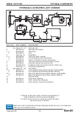
Страница 148: ...LOCATION PART NUMBER DESCRIPTION Nuts bolts washers and all other components can be ordered by physical description NOTICE 4 4 3 3 2 1 5 2 1 980 300185 Hydraulic Last Chance Control Bar 2 a 900 7900...

Страница 149: ...e Page 116 Relief Block 5 a 900 3925 04 Yoke Lift Cylinder Welded b 904 0007 14 Pin For Welded Cylinder Not Shown c 904 0006 90 Seal Kit Welded Lift Cylinder Not Shown 6 900 3927 73 Yoke Lift Control...

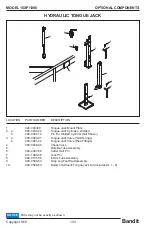
Страница 150: ...00 3934 24 Tongue Jack Cylinder Welded b 904 0007 14 Pin For Welded Cylinder Not Shown 3 a 900 3920 01 Tongue Jack Valve SAE O rings b 900 3901 42 Tongue Jack Valve Pipe Fittings 4 900 3949 09 Check V...

Страница 151: ...n be ordered by physical description NOTICE LOCATION PART NUMBER DESCRIPTION PIVOTING TONGUE 1 955 1015 32A Pivoting Lock Pin 2 980 0510 37 Pivoting Tongue Pin 3 980 0510 45 6 Pivoting Tongue Assembly...

Страница 152: ...Bandit 136 Copyright 9 18 MODEL 15XP 1390 Parts may not be exactly as shown NOTICE HYDRAULIC BUMP BAR Version 2 1 4 5 5 6 7 8 6 7 8 2 3 11 10 9 10 11 9 14 12 13 OPTIONAL COMPONENTS...

Страница 153: ...00 4906 54 3 8 16NC x 3 4 Bolt 6 900 4906 84 1 2 13NC Lock Nut 7 900 4906 88 1 2 Flat Washer 8 900 4906 73 1 2 13 x 1 3 4 Bolt 9 a 980 3011 43 Spring Tube for Spring Assist Single Springs b 937 3009 6...

Страница 154: ...Bandit 138 Copyright 9 18 MODEL 15XP 1390 Parts may not be exactly as shown NOTICE HYDRAULIC BUMP BAR OPTIONAL COMPONENTS 3 3 4 5 2 7 3 3 6 1 11 8 9 10 9 11 10...

Страница 155: ...p Bar Assembly 64 8 a 980 2003 37 Bump Bar Infeed Tray Assembly 35 b 626 2001 26 Bump Bar Infeed Tray Assembly 42 c 905 2000 56 Bump Bar Infeed Tray Assembly 45 d 917 2000 20 Bump Bar Infeed Tray Asse...

Страница 156: ...Bandit 140 Copyright 9 18 MODEL 15XP 1390 SERVICE RECORD SERVICE RECORD DATE DESCRIPTION AMOUNT...

Страница 157: ...BANDIT CONTROLS 1 245774458290 21Dec2016 HAND FED BANDIT CONTROLS FUEL SAVER RADIO WINCH w FEED ASSIST DUMP VALVE BUMP BAR...

Страница 158: ...switch to prevent grinding the starter while the engine is running If the engine does not start immediately it may be necessary to cycle the key back to the OFF position wait 15 20sec allow engine EC...

Страница 159: ...the Display C1 will default to Radio mode If C1 loses comm with the Display AND the radio receiver it will default to Tether Mode If C1 loses comm with display and receiver and tether it will remain...

Страница 160: ...ys defaults to AutoFeed ON when the key is first turned on A popup alert indicating the controls are in Bypass will blink on every screen because certain control features are disabled while in Bypass...

Страница 161: ...of 15 until keyswitch is cycled and that memory is cleared This is to provide a limited history of errors in case an operator is unable to watch this screen continuously and likely miss a status value...

Страница 162: ...gnosed for open broken connection while the output is de engergized The Outputs in Controller1 C1 are organized into 2 groups each group has a supply fuse The status of each fuse is shown at the top o...

Страница 163: ...load conditions simply press Throttle Up and then press Feed Fwd to resume feeding If the Winch Stow Switch indicates that the winch is out Feed Fwd will stop automatically and the Radio Winch functio...

Страница 164: ...idles down due to light load conditions simply press Throttle Up and then press Feed Fwd to resume feeding If the Winch Stow Switch indicates that the winch is out Feed Fwd will stop automatically and...

Страница 165: ...s The first number behind the Fan Rev Interval time setting is the engine fan state 0 neutral 1 pulling forward 14 reversing purge The second number behind the time setting is an error count of how ma...

Страница 166: ...PM to recover above AutoFeed Hi 2000rpm and then Feed Fwd will resume Note if AutoFeed Hi setting value is mistakenly set higher than the engine can run the Feed system will not Feed Fwd because it is...

Страница 167: ...normal operation the load on the engine might range from 50 90 while chipping When no material is being fed into the chipper it will just run at high rpm but maybe only 35 load With actual load being...

Страница 168: ...must see a 12V signal from the Winch Stow Switch a 0V signal from Feed Assist Push Button Switch When the operator is finished with winch operations the winch rope must be stowed properly to tighten...

Страница 169: ...signal from Feed Assist Joystick Feed Fwd When the operator is finished with winch operations the winch rope must be stowed properly to tighten down on the Stow Bar The Stow Switch will now indicate t...

Страница 170: ...p menu Popup menu disappears after 5sec Popup Menu Options 1 Press this button for Display Menu 2 Press for DPF Options If equipped with relevant T4 engine 3 Press to view System Faults 4 Press to cha...

Страница 171: ...58290 21Dec2016 Display Menu 1 Select down to the parameter you wish to adjust 3 4 Increase or decrease the value of the selected parameter or select through various options 5 Go back Engine ECU addre...

Страница 172: ...onment Exhaust gas temperature is high Auto Regen is in process of burning out accumulated soot Soot level in the DPF indicates need for Regen if in Auto the engine typically conducts the regen on its...

Страница 173: ...Go back If the engine or other system controller sends a diagnostic message as shown at right it will appear as a popup error with applicable details The popup message can be hidden press button 5 wh...

Страница 174: ...ANDIT CONTROLS 18 245774458290 21Dec2016 Faults and Diagnostic Messages The Amber LED corresponds to a Diagnostic Warning Condition The Red LED corresponds to a Diagnostic Stop Condition ie stop engin...

Страница 175: ...21Dec2016 Service Reminders 1 Select down to the parameter you wish to adjust 3 4 Increase or decrease the value of the selected parameter or select through various options 5 Go back 1 2 3 4 5 Press...

Страница 176: ...2016 Other Engine Parameters The engine may send information on other parameters it is monitoring These can be read on 1 of 4 engine pages Cycle through the engine pages to return to the Main Page Pre...

Страница 177: ...ting a laptop to the engine with certain engine service tools ex CAT ET etc it may be necessary to disconnect the main Controller by unplugging the 3amp VBBs fuse in station 3 The engine can still Key...

Страница 178: ...6 Bump Bar Option If the Chipper is equipped with a Bump Bar and Bump Bar Bypass valve a Bypass Button is connected to the valve which together allow Feed Fwd for 5 seconds even if the Bump Bar has di...

Страница 179: ...els these faults will trigger the engine to idle down and request action from the operator engine may also derate or shutdown in severe cases SPN FMI 3251 0 cu DPF is full of soot Contact engine servi...

Страница 180: ...t02 EStop BadCount04 TetherEStop counts only while in TetherMode The buttons on the infeed are tied into Throttle Up when FuelSave is turned on Winch In Out Sw R to Gnd Open 60 000 In 0 0 Out 1000 Ato...

Страница 181: ...BANDIT CONTROLS 25 245774458290 21Dec2016 Document notes 21Dec2016 First Draft...

Отзывы: