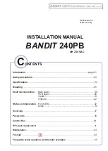


p.9 - PCB layout
PCB layout
BANDIT
240 PB
v.408
L
N
N
N
P
ri
m
.
tr
a
n
s
fo
S
e
c
.
T
ra
n
s
fo
H
e
a
te
r
7
5
0
W
h
e
a
te
x
c
h
a
n
g
e
r
2
3
0
V
A
C
P
o
w
e
r
s
u
p
p
ly
6
.3
A
T
1.25AT
5
0
0
m
A
T
F1
4AT
red
JMP
F2
F
3
F
4
Programmable
output n° 2
Programmable
output n° 1
Technical OK
output
Tamper loop
output [Tmpout]
Programmable
input n° 3
Programmable
input n° 4
Programmable
input n° 2
Programmable
input n° 1
12 V
DC
supply
(max. 500 mA)
Mains power supply
connection block with
integrated fuse
(4 AT)
Mains power connecting
cable, min 1.5 mm²
1
2
V
=
+
+
+
+
+
c
c
c
c
c
c
-
-
-
-
-
S
u
p
p
ly
X
in
1
X
in
2
X
in
3
X
in
4
T
m
p
o
u
t
O
K
o
u
t
O
K
o
u
t
X
o
u
t1
X
o
u
t2
X
+
X
+
X
+
X
+
T
a
c
o
m
c
o
m
c
o
m
n
c
n
c
n
c
n
c
n
c
n
c
n
o
n
o
n
o
n
o
n
o
n
o
X
-
X
-
X
-
X
-
T
b
5
0
0
m
A
.
in
p
u
ts
:
1
2
V
=
/
1
0
m
A
.
o
u
tp
u
ts
:
m
a
x
im
u
m
2
4
V
/
1
A
.
Red
White
Green
Blue
Yellow
Black
6 x Control box
PCB connector
Remote control
PCB-connector
Real Time
Clock
click-on
battery
Yellow PWM
heating
Led
Non-touchable mains
voltage zone
Rear cover tamper
spring switch


