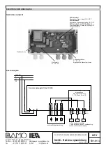
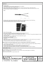
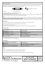
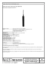
BAMO IER NivOil Скачать руководство пользователя страница 24

CABLE EXTENSION

The separately available cable clamp tube CET03 can be used to easily extend the connection cable. The clamping tube may be used as
simple aparatus in potentially explosive areas (including zone 1/ category 2).

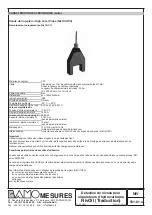
Shipment includes two WAGO 222
terminals

Ex marking

㐀 II 2G Ex ib IIB T4 Gb

The clamps have CAGE clamp connections with operating levers.
max. wire cross-section: 4mm²; conductor type = e+f

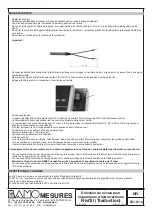
The cable shield of the extension cable is not connected. The two end plugs have an O-ring seal and must be inserted completely into the pipe
after the cable connection as far as it will go, then the cable glands must be tightened.

Note!

The protection class IP65 according to EN 60529 of the connection cable extension is not suitable for permanent immersion in oil separators!

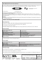
ALARM OIL, HIGH LEVEL AND SLUDGE LEVEL PROBE

Alarm delay

In order to avoid false alarms, an alarm is only signalled when it is permanently present for a longer period of time.

For the oil probe (NivOil OP) and the high level probes (NivOil HP / HPS) 10 seconds.

For the sludge probe (NivOil SP) 15 minutes.
In the first 15 minutes after switching on, the sludge probe (NivOil SP) reacts after only 10 seconds for testing purposes.
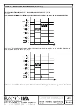
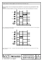
Operating states

Control Unit (NivOil CU)

Status of the probe

Channel 1, 2 or 3

No LED lights up; relay de-energised

No probe registered

Green LED lights up

Probe logged in ready for operation

Red LED blinking; relay de-energised; buzzer on

Alarm is currently reported

Red LED lights up; Relay de-energised

Alarm is currently signalled and alarm was acknowledged

One green LED is blinking

Alarm was not acknowledged and
Alarm has disappeared again

For further explanations, see also the following diagrams
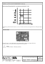
Error signals

Sensor supply unit / Control unit (NivOil CU)

Status of the probe

Channel 1, 2 or 3

No LED is lit

No probe is registered due to cable breakage or incorrect polarity

One green LED blinking; relay de-energised; buzzer on

Short circuit or interruption of the sensor circuit

All 3 green LEDs blinking; relay de-energised; buzzer on

Incorrect or defective probe

Reset

If a probe is disconnected or reconnected, the inventory list must be read in again.

Press the reset button until the buzzer has beeped 5 times (approx. 5 seconds).

This logs out all probes for a short time, checks what is connected and adds it to the inventory list accordingly.

LEV

21-03-2023

M-531.01-EN-AI

OIL/LIGHT LIQUID

SEPARATOR MONITORING

NivOil - (translation)

22, Rue de la Voie des Bans · Z.I. de la gare · 95100 ARGENTEUIL

Tel

Fax

+33 (0)1 30 25 83 20

+33 (0)1 34 10 16 05

Web

E-mail

www.bamo.eu

export@bamo.fr

INTERNATIONAL

531-01


/24

Содержание NivOil

Страница 1: ...01 Ind AI Bedienungsanleitung Operatinginstructions Translation Mise en service Traduction DE EN FR l Leichtflu ssigkeitsabscheider berwachung Alarmsystem for oil water separators D tection de niveau...

Страница 2: ...bflusssystems Sobald das zulaufende Wasser einen zu hohen Pegel erreicht hat wird eine Alarmmeldung ausgel st Die alternative Aufstausonde Typ NivOil HPS BVS 09 ATEX E 021 X erkennt eine Verstopfung d...

Страница 3: ...ienung Folientaster f r Test und Hupenquittierung interner 4 fach DIP Schalter Alarmrelais 3 Ausgangsrelais 230V AC 3A pro Messkanal ist jeweils ein potentialfreier Wechslerkontakt zugeordnet Relaisko...

Страница 4: ...ine gemischten Parameter Ex Kennzeichnung II 1G Ex ia IIB T4 Ga eigensicheres elektrisches Betriebsmittel Zusammenschaltung Sensorspeiseger t NivOil CU mit lsonde NivOil OP Besondere Bedingungen f r d...

Страница 5: ...er Ex Kennzeichnung II 1G Ex ia IIB T3 eigensicheres elektrisches Betriebsmittel Zusammenschaltung Sensorspeiseger t NivOil CU mit Aufstausonde NivOil HP Besondere Bedingungen f r die sichere Anwendun...

Страница 6: ...gsam flie enden Medien einsetzen Starke mechanische St e auf das Sondengeh use m ssen bei der Montage bei Wartungsarbeiten und im Betrieb vermieden werden Nur feucht reinigen elektrostatische Aufladun...

Страница 7: ...sam flie enden Medien einsetzen Starke mechanische St e auf das Sondengeh use m ssen bei der Montage bei Wartungsarbeiten und im Betrieb vermieden werden Nur feucht reinigen elektrostatische Aufladung...

Страница 8: ...punkt Sie dienen zum einfachen Einstellen des gew nschten Alarmpunktes Aufstausonde NivOil HP In der Einlaufkammer montieren die seitliche Bohrung muss auf der H he des gew nschten max zul ssigen Aufs...

Страница 9: ...andsliste Beim erstmaligen Zuschalten merkt sich die Elektronik in einer Bestandsliste welche Sonde an welchem Eingang angeschlossen ist Bei der Pr fung wird 2x ein Signalton ausgegeben Werkseinstellu...

Страница 10: ...onde x 230V AC L N PE Sensorspeiseger t NivOil CU Eingangsstromkreise E1 E3 nach Ex ia IIB Sonde x Sonde x L N S1 S2 S3 E1 E2 E3 NC C NO NC C NO NC C NO blau braun blau braun blau braun externe Signal...

Страница 11: ...iert die Schlammsonde NivOil SP f r Pr fzwecke schon nach 10 Sekunden Betriebszust nde Sensorspeiseger t NivOil CU Zustand der Sonde Kanal 1 2 oder 3 Keine LED leuchtet Relais abgefallen Keine Sonde a...

Страница 12: ...ine zum Beispiel durch Wellenbewegung der Fl ssigkeitsoberfl che die blinkende gr ne LED wird danach mit der RESET Taste quittiert EIN AUS EIN AUS EIN AUS EIN AUS EIN AUS EIN AUS ALARM LED gr n LED ro...

Страница 13: ...rote LED beginnt wieder zu blinken ST RUNGSHUPE Mit dem DIP Schalter 1 auf der Elektronikplatine im Sensorspeiseger t kann die Hupe dauerhaft ausgeschaltet werden Der Alarm wird dann nur noch optisch...

Страница 14: ...ie Sonden gereinigt werden Die Sonden k nnen dazu mit handels blichen fettl senden Reinigern vom anhaftenden Fett lfilm befreit werden Beachten Bei der Reinigung darf es zu keinen elektrostatischen Au...

Страница 15: ...detects a blockage of the drainage system An alarm signal is triggered as soon as the inflowing water has reached a level that is too high The alternative high level probe type NivOil HPS BVS 09 ATEX...

Страница 16: ...brane push button for test and buzzer acknowledgement internal 4 fold DIP switch Alarm relay 3 output relays 230V AC 3A one potential free changeover contact assigned to each measuring channel Relay c...

Страница 17: ...al inductance Li 0 3mH no mixed parameters Ex marking II 1G Ex ia IIB T4 Ga intrinsically safe electrical equipment Interconnection Sensor supply unit NivOil CU with oil probe NivOil OP Special condit...

Страница 18: ...rking II 1G Ex ia IIB T3 intrinsically safe electrical equipment Interconnection Sensor supply unit NivOil CU with overfill probe NivOil HP Special conditions for safe use The connection line of the h...

Страница 19: ...flowing media Strong mechanical impacts on the probe housing must be avoided during installation maintenance work and operation Clean only with a damp cloth avoid electrostatic discharges Special con...

Страница 20: ...ow flowing media Strong mechanical impacts on the probe housing must be avoided during installation maintenance work and operation Clean only with a damp cloth avoid electrostatic discharges Special c...

Страница 21: ...tching point They are used to easily set the desired alarm point High level probe NivOil HP Mount in the inlet chamber the lateral hole must be at the height of the desired max permissible accumulatio...

Страница 22: ...main switched off Inventory list When the unit is switched on for the first time the electronics remember which probe is connected to which input in an inventory list A signal tone is emitted 2x durin...

Страница 23: ...Sensor supply unit NivOil CU safety circuits E1 E3 according to Ex ia IIB Probe x Probe x L N S1 S2 S3 E1 E2 E3 NC C NO NC C NO NC C NO blue brown blue brown blue brown external signalling device x An...

Страница 24: ...Operating states Control Unit NivOil CU Status of the probe Channel 1 2 or 3 No LED lights up relay de energised No probe registered Green LED lights up Probe logged in ready for operation Red LED bli...

Страница 25: ...for example due to wave movement of the liquid surface the blinking green LED is then acknowledged with the RESET button ON OFF ON OFF ON OFF ON OFF ON OFF ON OFF ALARM LED green LED rot Audible alar...

Страница 26: ...w and the red LED starts blinking again AUDIBLE ALARM The buzzer can be switched off permanently with DIP switch 1 on the circuit board in the control unit The alarm is then only signalled visually an...

Страница 27: ...er cleaning the light liquid separator The probes can be cleaned of the adhesive grease oil film with commercially available grease dissolving cleaners Note Electrostatic discharging must be prevented...

Страница 28: ...teur anti d bordement NivOil High Level Probe HP BVS 07 ATEX E 092 X d tecte une obstruction du syst me d vacuation D s que l eau atteint un niveau trop lev une alarme est d clench e Le capteur anti d...

Страница 29: ...ir pour le test et l acquittement du klaxon Interrupteur DIP interne 4 positions Relais d alarme 3 relais de sortie 230V AC 3A un contact inverseur libre de potentiel est affect chaque canal de mesure...

Страница 30: ...tance interne maximale Li 0 3mH pas de param tres mixtes Marquage Ex II 1G Ex ia IIB T4 Ga mat riel lectrique de s curit intrins que Interconnexion Appareil d alimentation de capteurs NivOil CU avec s...

Страница 31: ...aximale Li 0 3mH pas de param tres mixtes Marquage Ex II 1G Ex ia IIB T3 mat riel lectrique de s curit intrins que Interconnexion Alimentation du capteur NivOil CU avec sonde de trop plein NivOil HP C...

Страница 32: ...t dans des milieux stagnants ou coulement lent Les chocs m caniques importants sur le bo tier de la sonde doivent tre vit s lors du montage des travaux de maintenance et du fonctionnement Nettoyer uni...

Страница 33: ...nt dans des milieux stagnants ou coulement lent Les chocs m caniques importants sur le bo tier de la sonde doivent tre vit s lors du montage des travaux de maintenance et du fonctionnement Nettoyer un...

Страница 34: ...e point d alarme souhait Sonde de trop plein NivOil HP Positionn dans la chambre d admission l extr mit de la sonde doit tre la hauteur du niveau de remplissage maximal autoris souhait Sonde de trop p...

Страница 35: ...3 LED clignotent Les canaux non utilis s restent d sactiv s Liste des sondes Lors de la premi re mise en marche l lectronique m morise dans une liste d inventaire quel capteur est raccord quelle entr...

Страница 36: ...Sonde x 230V AC L N PE Alimentation des capteurs NivOil CU Circuits d entr e E1 E3 selon Ex ia IIB Sonde x Sonde x L N S1 S2 S3 E1 E2 E3 NC C NO NC C NO NC C NO bleu brun bleu brun bleu brun Dispositi...

Страница 37: ...ndes fins de contr le tats de fonctionnement Alimentation du capteur NivOil CU tat de la sonde Canal 1 2 ou 3 Aucune LED n est allum e relais d sactiv Pas de sonde connect e LED verte allum e Sonde co...

Страница 38: ...m me par exemple en raison d un mouvement de la surface du liquide la LED verte clignotante est ensuite acquitt e par la touche RESET ON OFF ON OFF ON OFF ON OFF ON OFF ON OFF ALARME LED verte LED ro...

Страница 39: ...u et la LED rouge recommence clignoter AVERTISSEUR SONORE EN CAS D ALARME Le commutateur DIP 1 sur la carte lectronique permet de d sactiver l avertisseur sonore de mani re permanente L alarme n est a...

Страница 40: ...parateur Pour ce faire les sondes peuvent tre d barrass es du film de graisse d huile qui y adh re l aide de produits de nettoyage d graissants disponibles dans le commerce Important Le nettoyage ne...

Отзывы: