


ENGLISH
16 / 34
0006160178_201711
NATURAL GAS IGNITION AND REGULATION
• Check that there is water in the boiler and that the gate valves of
the system are open.
• Check that the discharge of combustion products through the boiler
gate and flue gate take places freely.
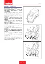
• Check that thee voltage on the mains meets the manufacturer
requirements and that all electrical connections made at the
installation site are performed properly as illustrated in our wiring
diagram.
• Prevent the second flame from functioning by disconnecting the 4
pole connector 4-pole connector from the electrical panel for TBG
45P-60P burners;
• Prevent the second flame from functioning by disconnecting the 4
pole connector 4-pole connector from the electrical panel for TBG
45P-60P burners;
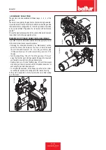
• Regulate air for the ignition flame:
- for TBG 45P - 60P burners with an electric servomotor,
follow the instructions given in drawing SERVOMOTOR CAM
ADJUSTMENT.
- for TBG 45P - 60P burners with an electric servomotor,
follow the instructions given in drawing SERVOMOTOR CAM
ADJUSTMENT.
• Open the combustion air regulator as necessary and open
approx. a third of the passage of air between head and flame
disk (diffuser). Operate the regulators incorporated in the safety
and operating valve in such a way as to obtain the gas delivery
presumed necessary.
• On models with a three-phase power supply, with the I/O switch
START/STOP switch on the burner panel in position “O” and the
general switch enabled, check by closing the contactor by hand
that the motor revolves in the correct direction.
• If necessary, invert the two cables of the line feeding the motor to
change the direction of rotation.
• Now switch on the switch START/STOP switch of the burner panel.
The control equipment thus receives voltage and the programmer
causes the burner to switch on as described in the chapter
“operation description”. During pre-ventilation, make sure that the
air pressure control switch changes its status (from the closed
position without pressure measurement to the closed position with
pressure measurement). If the air pressure switch does not detect
sufficient pressure, the ignition transformer is not switched on, nor
are the gas valves, and so the equipment is stopped in “lock-out”
mode.
• On first switching on repeated “lock outs” may occur due to the
following reasons:
• With the burner on at minimum you must carry out a check on
the combustion parameters, performing the necessary corrections
by means of the gas and air output regulators (see points 4 and
5). Subsequently a check is carried out on the quantity of gas
supplied, by reading the meter. If necessary the gas output and
the corresponding combustion air can be corrected as previously
described (points 4 and 5). Then check the combustion with the
suitable instruments. For a correct air/gas ratio you must find a
carbon dioxide (CO2) value for methane that is at least 8 % or O2
= 6 % at minimum burner output up to an optimal CO2 value of 10
% or O2 = 3 % for maximum output. It is essential to check, with a
suitable instrument, that the percentage of carbon monoxide (CO)
present in the fumes does not exceed the limit set by regulations in
force at the time of installation.
• Repeatedly check that the first flame is supplied correctly. After
adjusting operation with the first flame, turn off the burner, turn off
the main switch and switch on the electrical circuit that controls the
activation of the second flame: re-activate the 4 pole connector
previously disconnected for TBG 45P-60P burners.
• Repeatedly check that the first flame is supplied correctly. After
adjusting operation with the first flame, turn off the burner, turn off
the main switch and switch on the electrical circuit that controls the
activation of the second flame: re-connect the wire to the terminal
5 of the terminal board on the printed circuit which supplies the Y2
coil for TBG 45-60 burners.
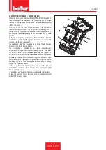
0002935620
2
8
7
1
5
10
6
9
4
3
Содержание TBG 45 P
Страница 2: ......
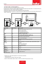
Страница 34: ...ITALIANO 32 34 0006160178_201711 SCHEMI ELETTRICI ...
Страница 35: ...ITALIANO 33 34 0006160178_201711 ...
Страница 68: ...ENGLISH 32 34 0006160178_201711 WIRING DIAGRAMS ...
Страница 69: ...ENGLISH 33 34 0006160178_201711 ...
Страница 71: ......


