NATURAL GAS IGNITION AND REGULATION
Carry out a check of the equipment before commissioning, after each
overhaul and after the equipment has been inactive for a long time.
Verify the combustion chamber does not contain gas before any igni
-
tion operation.
• Attempting a start up without introducing gas, verify a lock out stop
occurs at the end of the safety time (or more cycle repetitions up to
a maximum of 10, depending on the settings).
•
Interrupting the flow of gas with the equipment operating, verify that
voltage to the gas solenoid valves is cut within 1 sec., and after a
cycle repetition (or more repetitions up to a maximum of 10, de
-
pending on the settings), the equipment carries out a lock out stop.
• The time and cycle comply with those indicated for the type of equi-
pment used.
•
The flame signal level is sufficiently high.
• The ignition electrodes are regulated according to an air discharge
distance between 2 and 4 mm.
• The intervention of limiters or safety devices causes a shut down
or safety stop of the equipment according to the type of application
and modes foreseen.
•
Make sure that the combustion products may be freely vented
through the boiler and flue dampers.
• Make sure that the mains voltage corresponds to the manufactu-
rer's requirements and that all electrical connections made at the
installation site are effected properly as illustrated in our wiring dia-
gram.
•
Check that there is water in the boiler and that the gate valves of
the system are open.
•
Open the combustion air regulator as necessary and open approx.
a third of the passage of air between flame disk and head (diffu
-
ser). Act on the regulators incorporated in the safety and operating
valve in such a way as to obtain the gas delivery deemed to be
necessary.
•
Power the burner by connecting the main switch.
•
The burner is therefore activated and carries out the pre-ventilation
phase.
•
If the air pressure exceeds that value at which the air pressure
switch has been set, the ignition transformer will be connected and,
subsequently, the gas valves (safety and operating) will be inser
-
ted.
• The valves open completely and the gas delivery is limited to the
position at which the flow regulator incorporated in the main opera
-
ting valve has been manually regulated.
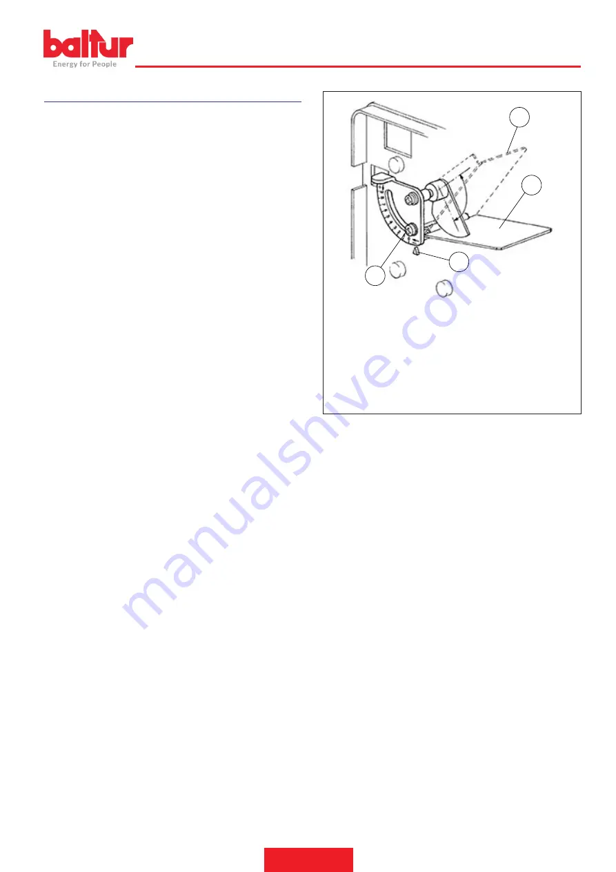
4
1
2
3
8922/2
1 Screw for adjusting air damper opening
2 Air damper opening reference index
3 Closed damper: reference index in position “0”
4 Damper fully open: reference index in position “0”
•
Upon first switching on, repeated “lock outs” may occur due to:
•
The gas pipeline has not been adequately purged of air and there
-
fore the quantity of gas is not sufficient to allow for a stable flame.
•
“Lock out” with flame presence could be caused by flame instability
in the ionisation area, due to an incorrect air/gas ratio.
•
This can be solved by changing the amount of air and/or gas sup
-
plied, so as to find the right ratio.
•
This problem could also be caused by an incorrect distribution of
air/gas in the combustion head.
•
This can be solved with the combustion head adjustment device by
further closing or opening the air passage between the combustion
head and gas diffuser, through the flame disk adjustment system.
•
It may occur that the ionisation current is disturbed by the dischar
-
ge current of the ignition transformer (the two currents have a com-
mon path on the burner’s “mass”). Therefore, the burner locks out
due to an insufficient ionisation.
•
This can be solved by verifying the correct position of the ignition
electrode.
•
A shut down with flame presence could also be caused by the bur
-
ner’s casing not being properly “grounded”.
• The minimum ionisation current value required for a correct opera-
tion of the equipment is indicated in the wiring diagram.
ENGLISH
11 / 28
0006160053_201912
Содержание BTG 12
Страница 2: ......
Страница 29: ...SCHEMI ELETTRICI ITALIANO 27 28 0006160053_201912...
Страница 57: ...WIRING DIAGRAMS ENGLISH 27 28 0006160053_201912...
Страница 59: ......


