44
M I S C EL LA N E O U S R EL AY S
SWITCH
WIRE
No.
"B" cam
relay co il
A
- 1 3
8 0 - 2 0
7 0
1
N . c .
C-
14
2
N . c .
C - 1 3
3
N . c .
J-40
2 5 - 6
3 0- 2 0
4 0 - 1 3
4 5 - 5
18-4
54-7
"e"
cam
co il
A-14
3 0 - 2 0
7 0
1
N . c .
2
N . C .
N . c .
B - 1 3
J-4 1
C - 1 3
1 3 - 5
4 0 - 1 3
5 4 - 7
5 0 - 14
8 0 - 2 0
4 8 - 5
Li fter start
coil
A
- 3 7
3 8 -8
7 0
Ll
L 2
Rl
R2
R3
R4
2 0 - 1 3
N . o .
F - 1 2
14 - 1 7
6 1 - 7
S . P . D . T .
D
- 1 2
5 3 - 18
3 6
N . o .
D
-
3 7
3 8 - 8
1 0 - 1 3
N . C .
E-ll
1 5 -6
5 8 - 1 3
N . c .
D-ll
3 1 - 3
5 6 - 9
N . C .
E-8
18 - 3
W I RE COLORS
Black
Orange
Blue-White
Yellow
Green
Green-Whi te
Red-Black
White-Green
Yel low
Red-Yellow
Green
White-Green
White
Black
Green-Black
Ye llow-Black
Blue
Red Green
Brown-Red
White-Ye llow
Yellow-Brown
Yellow-Black
Red
Red-White
White-B lack
Yellow-Red
White-Brown
Red-Black
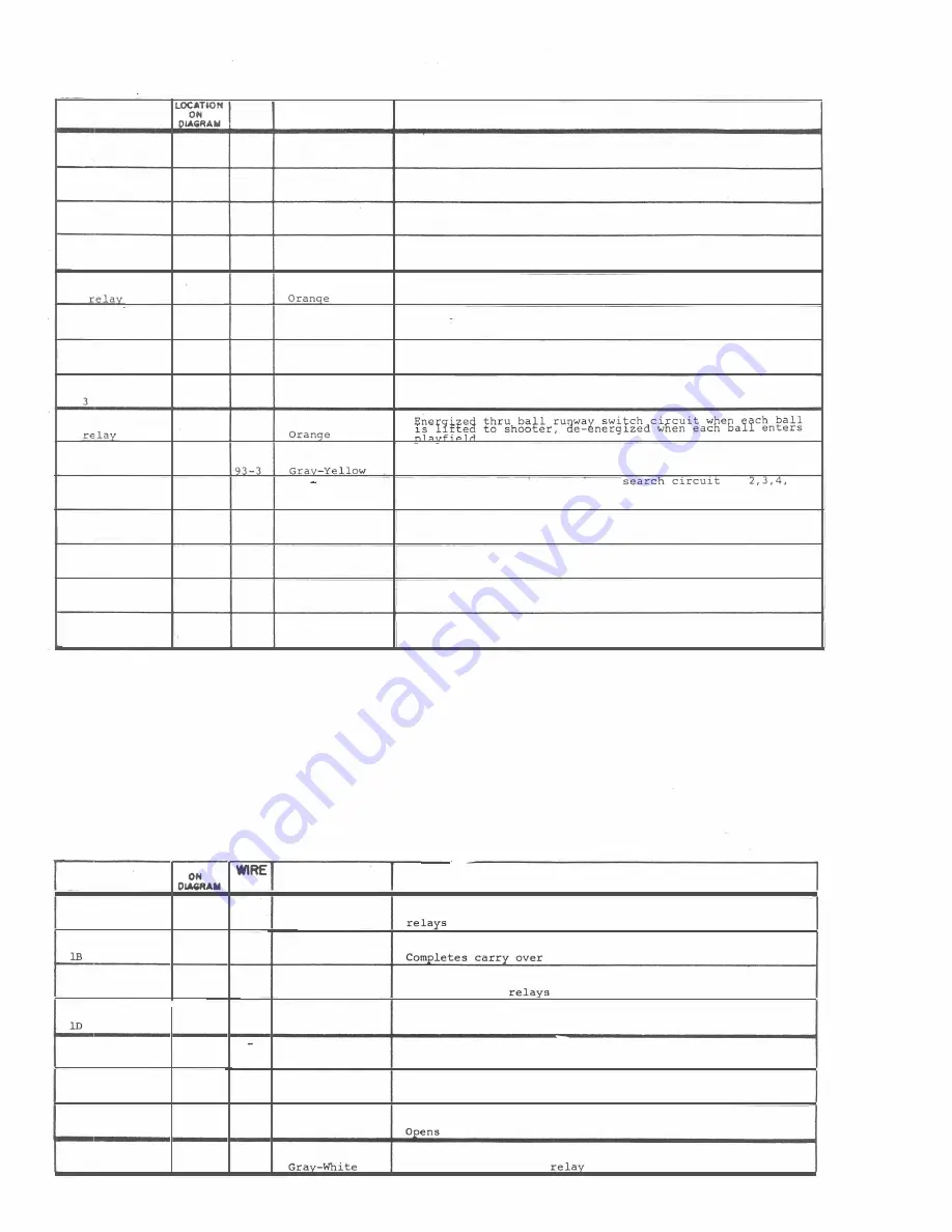
FUNCTION OF SWITCHES
Energized thru mystic l ines feature disc circuit by "BII
button switch
Opens mystic lines feature disc "CO button circuit
Opens mystic
1
in"'!
5
feature disc " A" button circuit.
Opens circuit to search relays
Energized thru mystic lines feature disc circuit by " CO
button switch
Opens mystic lines feature disc " A" button circuit
Opens circuit to search relays
Opens mystic lines feature disc "B" button circuit .
I����e��a w��t��t£�ge�i���I�rIo�ui��Gl��r����swrgn��ve
search
Directs
5
ball d�amond w�nner
or
ball diamond winner search circuit, thru "R" button .
Completes lock in circuit to thi s relay
Opens ball count circuit to the lockout re lays while relay
is energized
Opens ball count circuit to ball l ifter motor whi le relay
is energized
Opens timer disc c ircuit to shutter motor while re lay is
energized
BALL LI FTE R M OTO R U N IT
SWITCH
�TlOH
W I RE COLORS
FUNCTION
OF
SWITCH ES
No.
15-6
Red-White
Opens balJ.
count circuit to the
selection
lockout
trip
lA
N . c .
0- 1 2
8 5
-6
Black-White
91-1
Gray-Red
N . o .
C-ll
30
Yellow
circuit
to motor
57-7
White-Orange
In series with
shutter
motor
circuits
from timer unit , anti-
lC
s . c .
0-6
5 3 - 5
White-Yellow
cheat and
tilt
21-3
Blue-Red
N . o .
F-ll
5
1
-
3
White-Red
Completes
lock in circuit
to bal l detector
relay
43
2
Green-Yellow
2A
N . o .
E-7
27-2
Blue-Orange
Completes
o
thru 5th step
timer unit step up circuit
9
3
-
17
Gray-Yellow
2B
N . o .
E-9
14-5
Red-Green
Completes ball detector
re lay
circuit
to tilt trip relay
21-3
B lue-Red
2C
N . c .
0-57
5 2-4
White-Blue
lock in
circuit to ball
lift relay
Pin
Sw.
4 8 - 2
Green-Black
3A
N . c .
G-4
95-3
In
series
with start
circuits


