31
BAE PD-VS-014-05
Network topologies
For the startup of the Balluff SmartVision Controller, it is first integrated in the network environment. The different options
are described in the following examples. This covers a large part of the application cases. To operate the Ball-
uff SmartVision Controller
requires that the supply voltage is provided via the power connection in any case.
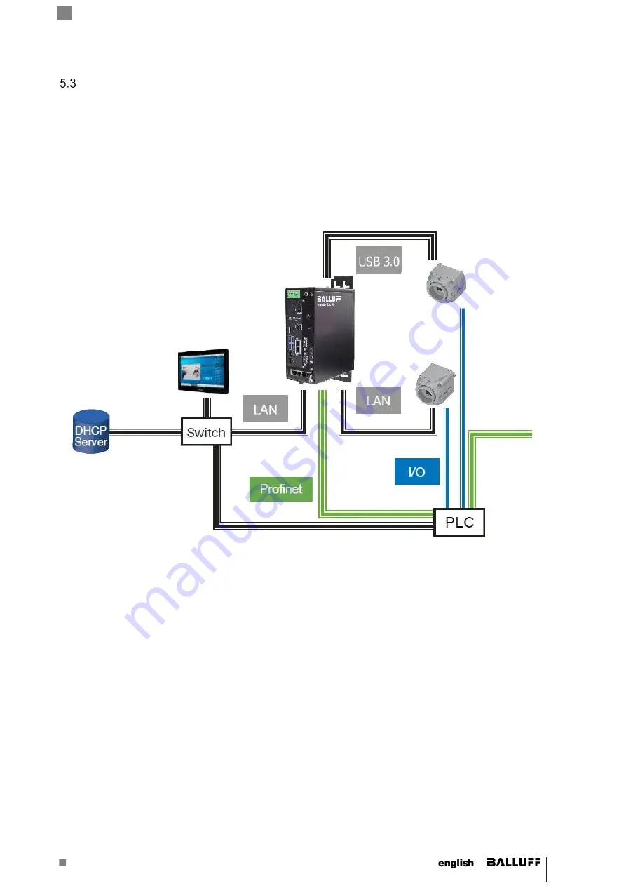
The example shows the integration of the Balluff SmartVision Controller into an existing network with DHCP via the Giga-
bit Ethernet (LAN) female connector 1. The IP address is dynamically assigned. GigE Vision cameras can be connected
using the Gigabit Ethernet (industrial cameras) connectors and / or USB3 Vision cameras using the USB 3.0 (industrial
cameras) connectors. The interaction of the industrial cameras with the system and the analyzing of a control is done via
the digital I/Os; the interaction of the Balluff SmartVision Controller via the Gigabit Ethernet (LAN) conntector or the
fieldbus. This allows, e.g. to initiate the trigger or query the status of the Balluff SmartVision Controller or the industrial
camera.
The integration of the Balluff SmartVision Controller into an existing network can be made using fixed IPs. However,
please keep in mind, that IP addresses can only be used once.
5.3.1
Bandwidth limit of switches (multi-camera operation with Gigabit Ethernet)
When 4 Gigabit Ethernet cameras are used in parallel operation, we do not recommend to use a switch because of the
bandwidth limit of switches but to connect each camera to one of the four Gigabit Ethernet (LAN) conntectors. Using 8
Gigabit Ethernet cameras we recomend to use 4 switches each with 2 cameras connected. Each switch should then be
connected to one of the four Gigabit Ethernet (LAN) conntectors.
Содержание SmartVision BAE PD-VS-014-05
Страница 1: ...BAE PD VS 014 05 SmartVision Controller...
Страница 2: ......


