


www.balluff.com
25
5
Commissioning
BVS SC-_1280Z00-07-0_0
SMART
CAMERA
IO
english
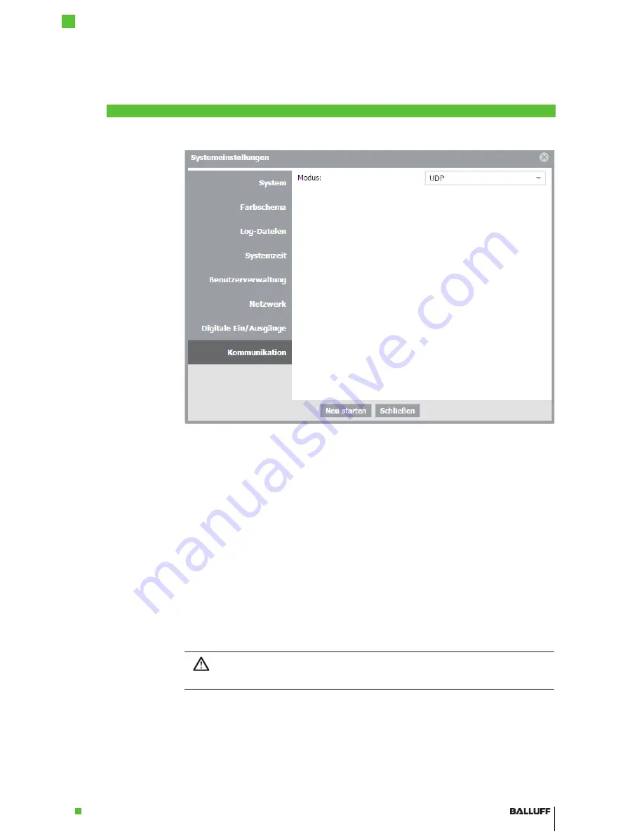
Figure 23: Communication tab in the System settings
All variants of the
SMART
CAMERA
feature a 1 Gbit/s LAN interface for configuring and monito-
ring the image analysis. Chapter “First Steps” on page 21 describes how this interface is used
to establish the connection between computer and
SMART
CAMERA
. For some network topolo-
gies, this simple description is not sufficient. The required steps are described below.
SMART
CAMERA
and PC are in different subnets of the network
Subnets are explicitly created to be able to subdivide computers in different networks and to
structure it in this way. Since the different subnets, on the other hand, are connected via swit-
ches, the communication with the
SMART
CAMERA
is still possible. In most networks, it is only
necessary to enter the URL http://sc-150800015de with the matching serial number in the
address field of the browser. The connection is established automatically. The
SMART
CAMERA
obtains the IP address from the DHCP server and the name service of the network ensures that
the URL with the serial number is replaced with the correct IP address.
Without a name service, the URL cannot be resolved! In this case, the IP address must be
entered directly. To do so, it is recommended to configure the DHCP server in such a way that
the
SMART
CAMERA
is assigned the same address in every case. As an alternative, the IP
address can also be assigned manually (see the next section).
Notice!
It must be ensured that no IP exists multiple times in the network in order to avoid any
address conflicts!
5.4
Network Set-
tings / LAN
Interface
5.5
Locating the
Camera in the
Network


