background image

www.balluff.com

21

4

First Steps

BVS SC-_1280Z00-07-0_0

SMART

CAMERA

 IO

english

Three simple steps are required to initially start up and configure the 

SMART

CAMERA

. Besides 

the 

SMART

CAMERA

, the following is required:

–  Power cable
–  24 V power supply
–  LAN cable
–  PC with web browser
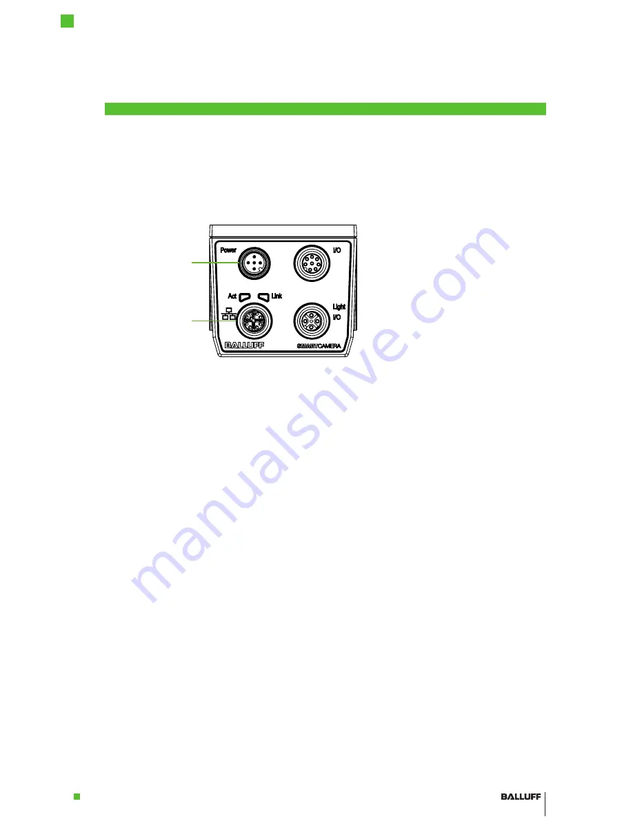
1

2

1

2

Power  

LAN

Figure 18:  Establishing a network connection with the 

SMART

CAMERA

Connect the 

SMART

CAMERA

 via the 

LAN

 port with the network.

Depending on the network topology between computer and 

SMART

CAMERA

, different network 

settings must be made on the computer. 
In general, the network configuration of your computer is set to "Obtain an IP address automati-

cally". For the firewall setting, Port 80 should be enabled.

The following network structures are possible:
– 

SMART

CAMERA

 and PC are connected directly via a LAN cable

IP addresses are set automatically

– 

SMART

CAMERA

 and PC are in the same subnet of a local network and a DHCP 

server is available for automatic IP assignment

IP addresses are set automatically

– 

SMART

CAMERA

 and PC are in the same subnet of a local network and no DHCP 

server is available for automatic IP assignment

In this case, the IP addresses of PC and 

SMART

CAMERA

 must be matched and manually 

set. Pertinent useful notes are located in the section “Network Settings / LAN Interface” on 

page 25.

– 

SMART

CAMERA

 and PC are in different subnets of a local network

Subnets are explicitly created to be able to subdivide computers in different networks and to 

structure it in this way. Since the different subnets, on the other hand, are connected via 

switches, the communication with the 

SMART

CAMERA

 is still possible. Pertinent useful 

notes are located in the section “Network Settings / LAN Interface” on page 25.

Now connect the power supply at the 

Power

 port with the power supply (24 V).

The 

SMART

CAMERA

 starts up and is operational after approx. 30 seconds.

At the start, the 

SMART

CAMERA

 opens the most recently opened inspection program and is in 

the same process state it occupied at switch-off.

4.1 

Step 1: 

 Establishing  a 

network con-

nection with 

the 

SMART-

CAMERA

4.2 

Step 2: 

 Switching  on 

the 

SMART-

CAMERA

Содержание BVS SC-C1280Z00-07-000

Страница 1: ...english BVS SC _1280Z00 07 0_0 SMARTCAMERA IO User s Guide...

Страница 2: ...pied or modified without prior written permission from Balluff All the trademarks and names appearing here are for identification purposes only Some of these trademarks may be regi stered trademarks o...

Страница 3: ...and Pin Assignment 12 3 6 Display elements 20 3 7 Cleaning 20 4 First Steps 21 4 1 Step 1 Establishing a network connection with the SMART CAMERA 21 4 2 Step 2 Switching on the SMARTCAMERA 21 4 3 Step...

Страница 4: ...f camera without additional software Easiest user supporting operation Support of Industry 4 0 through IO Link Separate data channel for larger data volumes Integrated flexible displays of process sta...

Страница 5: ...lluff Vision Solution CMOS Complementary metal oxide semiconductor DCP Discovery and basic Configuration Protocol DHCP Dynamic Host Configuration Protocol DID Device ID I O port Digital input and outp...

Страница 6: ...orth referred to as GTC The provisioning of the soft ware is exclusively subject to the respective current GTC the conditions in these operating instructions as well as the regulations of the Balluff...

Страница 7: ...and manufactured in accordance with the applicable European directives CE conformity has been verified All approvals and certifications are no longer valid in the following cases Components are used...

Страница 8: ...SMARTCAMERA and work in the Balluff BVS Cockpit interface developed specifically for camera systems SMARTCAMERA BVS SC Image Acquisition Image Analysis Result output via corresponding interfaces Figur...

Страница 9: ...ments in accordance with IP67 45 43 4 54 Figure 3 BAM PC VS 023 1 BAM02NA Please note that only C mount lenses with a maximum diameter of 42mm and a length of 40mm can be used here The following acces...

Страница 10: ...stening optional accessories see chapter 7 2 Accessories 61 97 5 70 105 7 44 3 17 23 3 30 5 82 5 105 7 54 8 34 3 18 108 5 Figure 4 Mechanical connection dimensions in mm 60 9 28 5 69 5 24 97 5 4 x M4...

Страница 11: ...ox Degree of protection IP67 with connectors and protection tube Weight without lens Approx 360g Dimensions L B H without connector without lens 110 62 55mm Electrical data Supply voltage 24 V 20 LPS...

Страница 12: ...signals are available I O Light 2 I O signals and supply voltage output e g for an external lighting Information In order to ensure enclosure rating IP67 unused I O ports must be closed with cover ca...

Страница 13: ...1 Input output 4 I O 2 Input output 5 I O 3 Input output 6 I O 4 Input output 7 Common In e g GND PNP 24V NPN 8 I O 5 Input output Information These inputs outputs are galvanically decoupled from the...

Страница 14: ...les how inputs and outputs must be connected to obtain input and output function Information I Os of the same name are logically connected with each other When operating the I Os as output then e g I...

Страница 15: ...is sourcing so that the load between I O and GND must be switched accordingly The load is connected with supply voltage if 1 is being output 1 2 3 4 VDC I O 0 GND 24 V I O 1 Figure 8 PNP output conne...

Страница 16: ...output Voltage VP 24 V VDC VD 1 3 A max Voltage drop VD 2 V Among other things this makes it possible to easily connect lighting equipment to the SMART CAMERA Either the permanent voltage supply or t...

Страница 17: ...l 0 0 5V I O to VCommon In 2mA Signal 1 11 30V I O to VCommon In 2 8mA Delay 0 1 10 s 1 0 100 s Operation as output PNP NPN Voltage Signal 0 High resistance High resistance 100mA max Signal 1 24V VCom...

Страница 18: ...ed as output the output is connected with Common Out and the actuator PLC input or similar is supplied with it if 1 is being output The output is high resistance if 0 is being output 1 2 3 4 5 6 7 8 2...

Страница 19: ...nfigured as output the output is connected with Common Out and the actuator PLC input or similar is supplied with it if 1 is being output The output is high resistance if 0 is being output 1 2 3 4 5 6...

Страница 20: ...reen Inspection stopped or in configuration mode Illuminating red Fault Flashing red Firmware update active Signal LED Off Signal 0 Yellow lit Signal 1 The signal LED can indicate the status of any I...

Страница 21: ...assignment IP addresses are set automatically SMARTCAMERA and PC are in the same subnet of a local network and no DHCP server is available for automatic IP assignment In this case the IP addresses of...

Страница 22: ...e 2 To do so select the network folder to display all the network devices It also lists the connected SMARTCAMERA cameras 3 To open the configuration screen of the SMARTCAMERA perform the following st...

Страница 23: ...nection in any case The IO1 topology shows a simply design with an operating panel for the configuration of the SMARTCAMERA The interaction with the system is done exclusively via the digital I Os in...

Страница 24: ...It consists of the following menu items Menu item Meaning User login Camera selection System setting Help system The process data results of the image analysis control of the image acquisition are exc...

Страница 25: ...es the communication with the SMARTCAMERA is still possible In most networks it is only necessary to enter the URL http sc 150800015de with the matching serial number in the address field of the brows...

Страница 26: ...cally IP If a static IP address is to be used it can be entered here Gateway If a static IP address is to be used the gateway can be entered here This entry is optional if the same subnet is used excl...

Страница 27: ...C I O 0 GND I O 1 Vext I O 6 Trigger GND I O 7 Boost I O 0 Common Out I O 1 I O 2 I O 3 I O 4 Common IN I O 5 24 V 24 V Power I O Light I O Port I O 0 I O 1 I O 2 I O 3 I O 4 I O 5 I O 6 I O 7 Isolati...

Страница 28: ...ings They are transferred using the little endian format The lowest value byte is transferred first in this case There are three different categories of messages 1 Messages from the camera to the clie...

Страница 29: ...in bytes 4 UINT32 01hex Message ID The camera responds to it with its Connect message Length in bytes Structure Value Description 4 UINT32 42565350hex Magic Number 4 UINT32 04hex User data length in...

Страница 30: ...r overflow more input containers than inspections so that one input container was discarded or underflow more inspections than input containers so that one input container was used multiple times 4 Bu...

Страница 31: ...s message to receive a trigger Length in bytes Structure Value Description 4 UINT32 42565350hex Magic Number 4 UINT32 00hex User data length in bytes 4 UINT32 41hex Message ID It is sent from the clie...

Страница 32: ...BAM LS VS 004 C2 3 1614 2 C mount lens 16mm focal length BAM02FF BAM LS VS 004 C2 3 2514 2 C mount lens 25mm focal length BAM02FH BAM LS VS 004 C2 3 3514 2 C mount lens 35mm focal length BAM02FJ BAM...

Страница 33: ...able BCC0HZK BCC M418 E818 8X0 723 PS58N9 020 GigE cable RJ45 M12 2m BCC06K7 BCC M418 0000 2A 044 VX8825 020 IO interface M12 open 2m BCC032F BCC M415 0000 1A 003 PX0434 020 Power M12 open 2 m Note Fo...

Страница 34: ...www balluff com www balluff com Balluff GmbH Schurwaldstra e 9 73765 Neuhausen a d F Germany Phone 49 7158 173 0 Fax 49 7158 5010 balluff balluff de No 928007 EN C16 Subject to change...

Отзывы: