BIS V-6108 PROFINET
Processor Unit
74
english
7
Device Functions
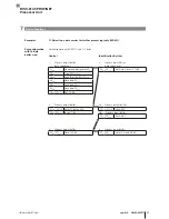
1. Reading 30 bytes at R/W head 1, start address 10
Once enough data has been read during the execution of the read job to fill the input buffer for
R/W Head 1, the data will be transmitted to the input buffer. The AE bit is not set until the
processor unit has finished the "Read" operation.
The "Job End" (AE bit) response is reliably set no later than before the last data has been sent.
This timing depends on the requested volume of data and the time response of the controller. In
the example, the use of italics for "
Set AE Bit
" calls your attention to this fact.
Control
Identification System
1.
Process output buffer
(note sequence):
2.
Process Input Buffer
(note sequence):
01
hex
Command designator 01
hex
00
hex
/0F
hex
Set AA bit
02
hex
Start address 0A
hex
01…0E
hex
Enter first 14 bytes
03
hex
Start address 00
hex
00
hex
/0F
hex
Invert TO bit
04
hex
No. of bytes 1E
hex
00
hex
/0F
hex
Set AE bit
05
hex
No. of bytes 00
hex
00
hex
/0F
hex
Set AV Bit
3.
Process input buffer:
4.
Process input buffer:
01…0E
hex
Copy first 14 bytes
01…0E
hex
Enter second 14 bytes
Process output buffer:
00
hex
/0F
hex
Invert TO bit
00
hex
/0F
hex
Invert TI bit
00
hex
/0F
hex
Set AE bit
5.
Process input buffer:
6.
Process input buffer:
01…0E
hex
Copy second 14 bytes
01…02
hex
Enter last bytes
Process output buffer:
00
hex
/0F
hex
Invert TO bit
00
hex
/0F
hex
Invert TI bit
00
hex
/0F
hex
Set AE bit
7.
Process input buffer:
8.
Process input buffer:
01…02
hex
Copy last bytes
00
hex
/0F
hex
Reset AA and AE bits
Process output buffer:
00
hex
/0F
hex
Reset AV bit
7.4 Examples


