10
english
5.2
Electrical connection
4-pin (supply)
3-pin (sensor)
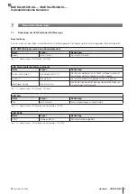
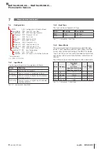
Fig. 5-2: Electrical connection for the amplifier (4-pin connection
only on variant -S75G)
Pin
Signal
Description
4-pin (supply) (plug variant)
1
VDC Operating voltage: 15…30 V
Max. current consumption: 45mA
2
AGND
– UA-S75G
– IC-S75G
0 V
IN
– UA-S75G-SA3
– IC-S75G-SA3
Input
(external teach, …)
3
GND Operating voltage: 0 V
4
AOUT
– UA-S75G
– UA-S75G-SA3
Voltage output:
0…10 V
– IC-S75G
– IC-S75G-SA3
Current output:
4…20 mA
5-pin (supply) (cable variant)
Braun
VDC Operating voltage: 15…30 V
Max. current consumption: 45mA
Weiß
AGND
– UA-DP02
– IC-DP02
0 V
Blau
GND Operating voltage: 0 V
Schwarz AOUT
– UA-DP02
Voltage output:
0…10 V
– IC-DP02
Current output:
4…20 mA
Rosa
IN
Input (external teach, …)
3-pin (sensor) (all versions)
1
LED+ Emitter (LED)
3
PHT+ Receiver (Photo transistor)
4
GND 0 V / Cable shielding
Tab. 5-1: Pin Assignment
Factory setting
Standard Power, Standard Speed, Syncmode Off,
Input Off
5.3
Shielding and cable routing
The BOH sensor cable is shielded and should not be
extended.
5.1
Installation
For dimensions, see drawings on page 8.
The following mounting types of the sensor amplifiers are
available:
Simple clamp mounting on DIN rail with dimension of
DIN 35 mm or 15 mm.
Screw mounting by means of through holes for M3
screws.
Clamp mounting on DIN rail adapter by means of M3
screws.
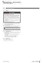
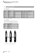
Place the device on the DIN rail adapter as shown. Con-
nect the cable according to the connection table.
Fig. 5-1: Mounting the amplifier
5
Installation and connection
BAE SA-OH-061-UA-... / BAE SA-OH-062-IC-...
Photoelectric Sensors
Содержание BAE SA-OH-061-UA-DP02
Страница 2: ...www balluff com ...
Страница 4: ...www balluff com ...
Страница 26: ...www balluff com ...
Страница 47: ......


