background image

MAINTENANCE

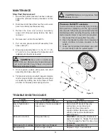
Replacing Power Spring:

1.  Be sure the system pressure has been relieved. 

Follow the pressure relief procedures.

2.  Disconnect inlet hose. Remove the reel to work 

bench and clamp reel base securely.
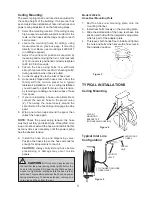
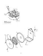
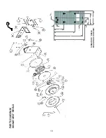
Wrapping hose

ROLLER OUTLET

DELIVERY

HOSE

HOSE

LOOP

BUMPER STOP

SIDE PANEL

HOSE LOOP

Figure 7

Pressure Relief Procedure:

To  reduce  the  risk  of  serious  bodily  injury, 

including fluid injection or splashing into the eyes 

and/or onto the skin, follow this procedure below 

before  maintaining  and/or  repairing  the  pump, 

solenoid and/or impulse meter or any part of your 

system.
1.  Disconnect the air supply from the pump.

2.  Open the dispensing valve into an approved 

waste  container  to  relieve  pressure  on  the 

system.

3.  Leave any bleed-type drain valves open until 

you are ready to use the system again.

6

MAINTENANCE

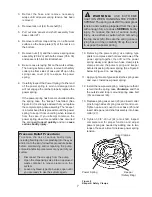
Replacing Service hose:

1.  Be  sure  the  pressure  supply  has  been 

relieved. 

Follow  the  pressure  relieve 

procedures below.

2.  Pull hose on reel down just enough to allow 

stop pawl to engage ratchet.  This will lock 

reel into position.

3.  Remove  the  dispensing  valve  and  hose 

stop.

4.  Wearing 

Heavy  Leather  Gloves

,  firmly 

grab the outside edge of the spool with both 

hands. Let the spool rotate slowly through 

your  hands  until  the  spool  stops.  When 

the  spool  stops  the  spring  tension  will  be 

released. The hose can now be unwrapped 

and removed from the reel.

5  From open side of reel begin to wrap new 

hose around spool in a clockwise direction.

6.  Pull  hose  out  through  roller  outlet  and 

reassemble  hose  bumper  stop  and 

dispensing Control Handle.

7.  Position the bumper stop so that the hose 

will extend enough so that all operators can 

reach it.


WARNING:


Wear  Heavy  Leather 

Gloves

 when replacing service hose and/or 

replacing power spring to protect your hands 

from injury.

!

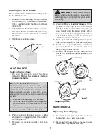
Installing the Derail Bracket

The derail bracket is included with all Signature 

Series DEF hose reels.
1.  Loosen the two mounting screws,indicated 

in  the  diagram,  to  allow  Derail  Bracket 

to  be  inserted  under  the  Mounting  Base 

(#824455).   

2.  Adjust  Derail  Bracket  to  allow  sufficient 

clearance for the Hose Reel to spin freely. 

Maximum  clearance  should  be  no  more 

than 1/4”.

3.  Retighten mounting screws.

Derail 

Bracket

Mounting Screws

Hose

Reel

Mounting Base

Содержание Signature DEF Series

Страница 1: ...N MAINTENANCE AND REPAIR GUIDE Thoroughly read and understand this manual before installing operating or servicing this equipment SERVICE BULLETIN SB2023 Rev C 7 11 Models 2400 006 Bare Reel 2400 007...

Страница 2: ...is strong enough to support the reels the weight of the fluids and the stress caused by hard pulls on the service hoses See page 3 for dry weights of the hose reel assemblies WARNING WARNING The MAXI...

Страница 3: ...Bare Reel Wetted Parts 2400 007 16 X 3 4 150 psi 8569 016 8562 003 2400 006 Stainless Steel Viton 2400 008 20 X 3 4 150 psi 8569 020 8562 003 2400 006 Stainless Steel Viton 2400 009 30 X 3 4 150 psi...

Страница 4: ...the power spring tension the hose must pull out fully and retract fully Wrap ONE more loop onto spool extend the hose and latch it Do this as many times as necessary until the power spring has the de...

Страница 5: ...e the stop pawl 8 Wrap one to two loops around the spool then retract the hose again CAUTION Do Not put so many loops onto the reel that the power spring winds tightly before the hose is fully extende...

Страница 6: ...s will lock reel into position 3 Remove the dispensing valve and hose stop 4 Wearing Heavy Leather Gloves firmly grab the outside edge of the spool with both hands Let the spool rotate slowly through...

Страница 7: ...r spring and keeper before disposing of power spring See Figure 8 below Figure 9 on next page 11 Apply a light coat of grease inside the spring case and cover Install new power spring 12 Install the n...

Страница 8: ...Figure 10 Spring Case Power Spring Vise Grip Pliers Figure 9 Power Spring Removal Using Locking Pliers 13 45 46 8...

Страница 9: ...the system again CAUTION Before servicing reduce fluid supply pressure to zero CAUTION Never alter or modify any parts of this reel Doing so may cause damage to reel and or personal injury Always use...

Страница 10: ...separately but it is recommended that the complete swivel be replaced if or when swivel fails Figure 12 45 46 8 8 44 x6 places 4 94 11 00 R 22 3 55 7 55 10 30 88 2 50 4 00 80 SIGNATURE REELS Mounting...

Страница 11: ...OT IN USE 2 x x x x 25 832923 1 Mounting Base 1 x x x x Parts Listing for Signature DEF Reel 2400 007 2400 008 2400 009 2400 006 ITEM PART DESCRIPTION QTY 26 832922 Outlet Arm 1 x x x x 27 832918 1 3...

Страница 12: ...of item 13 to six and removed item 24 NOT IN USE Rev C Added note about inlet connection on page 4 Balcrank Corporation 115 Reems Creek Road Weaverville NC 28787 800 747 5300 800 763 0840 Fax www bal...

Отзывы: