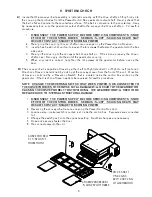
Open the front door and verify the proper orientation of the upper air return shield.
C)
The plenum
fingers are identical, so any finger can be mounted in any location.
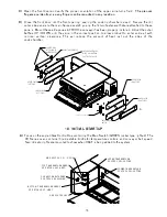
D) Close the front door into the front opening, sealing the cooking chamber closed. Secure the (4)
outer side panels to the main frame assembly using the ¼-turn fasteners that are attached to these
panels. Mount these side panelsAFTER the conveyor has been properly installed. Adjust the outer
baffles UP / DOWN until they are in the correct position to allow product to enter and exit with
minimal vertical clearance. This will reduce the amount of heat lost out the sides of the
cook chamber.
ADJUSTABLE BAFFLE
LOWER COVER
( LEFT SIDE )
H NGER PINS
( ATTACHED TO
UPPER COVER )
A
UPPER COVER
( RIGHT SIDE )
LOWER COVER
( RIGHT SIDE )
UPPER COVER
( LEFT SIDE )
ADJUSTABLE
BAFFLE
1/4-TURN FASTENERS
(2) TOP & (2) BOTTOM
( CAPTIVE TO COVER )
10
10. INITIAL STARTUP
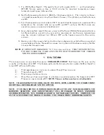
A) Focus on the angled Gas Control Box containing the Main Switch (GREEN rocker type, lighted). The
VH-Series oven contains (3) adjustable knobs for temperature controls and conveyor belt speed.
Two indicator lights are mounted to show when HEAT is being added to the system.
GAS CONTROL BOX
CONVEYOR BELT SPEED
CONTROL CW=SLOWER
TOP TEMPERATURE READY
INDICATOR LIGHT (HEAT)
MAIN SWITCH ON (I) OFF (0)
LOWER TEMPERATURE
CONTROL CW=HOTTER
BOTTOM TEMPERATURE READY
INDICATOR LIGHT (HEAT)
UPPER TEMPERATURE
CONTROL CW=HOTTER
FRAME SPREADER


